GuidesTools GearCareers Find a CFIFind a School About
Training Guide · Navigation
Student Pilot2026

How to Read a Sectional Chart

The sectional chart is your primary VFR navigation tool. Once you know what every symbol means, it becomes readable as a story of the airspace around you. Here's everything you need to know.

How to Read a Sectional Chart

A VFR sectional chart is a 1:500,000 scale aeronautical chart — one inch on the chart equals about 6.86 statute miles on the ground. Each chart covers roughly 340 × 340 miles and is updated every 56 days. Learning to read one is one of the most fundamental student pilot skills, and it's a topic the DPE will explore thoroughly during your oral exam.

The best way to learn a sectional is with a physical copy or high-resolution PDF open while reading this guide. You can download any current sectional for free from vfrmap.com or the FAA chart supplement.
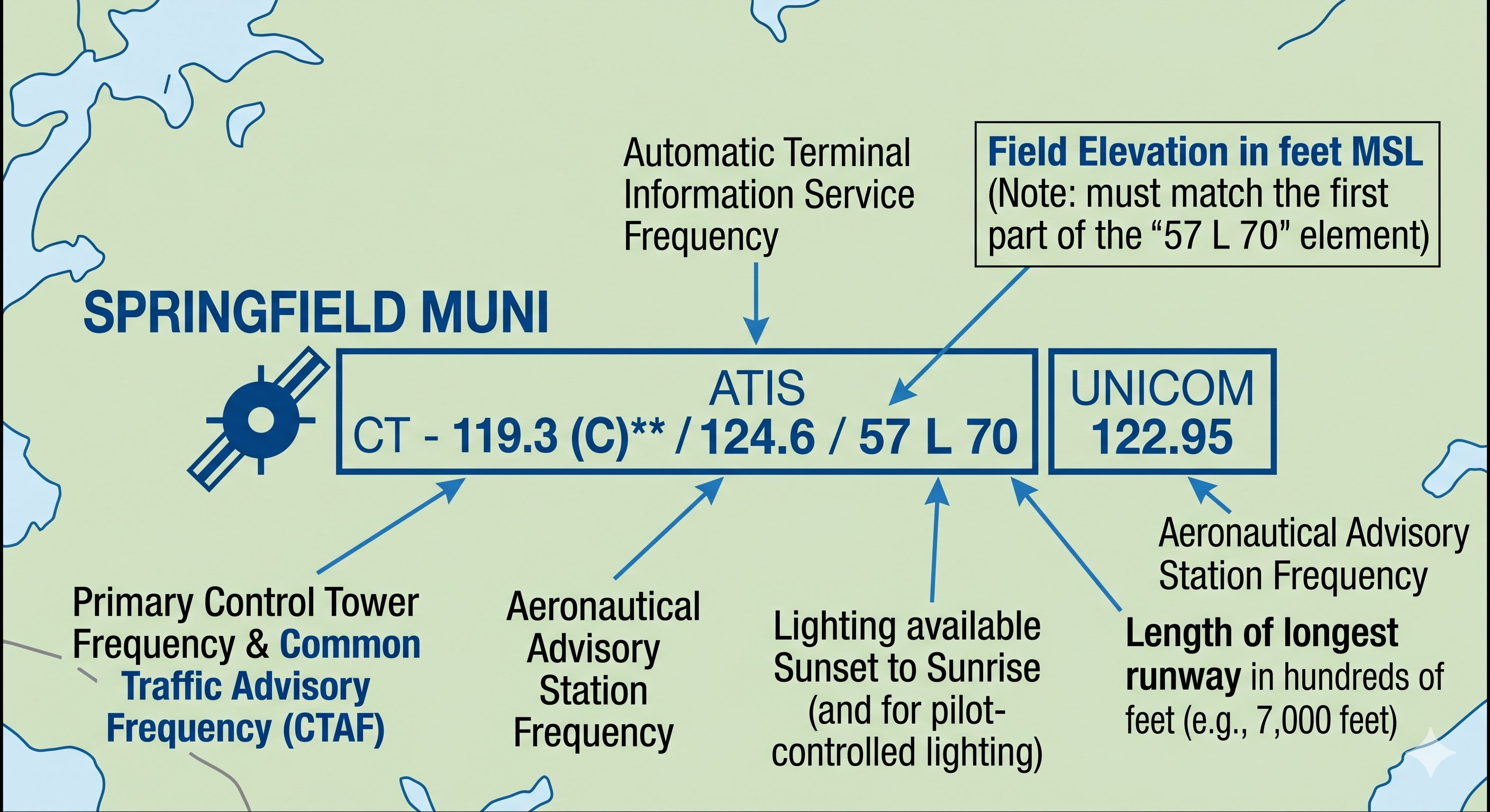
Airports — the most important symbols

Airport colors: blue vs. magenta

Blue airports have an operating control tower — they're in Class B, C, or D airspace. When flying to a blue airport, you'll need two-way radio communication before entering the airspace, and you'll receive specific landing clearance from the tower.

Magenta airports are non-towered (no control tower, or tower is part-time). You self-announce on the Common Traffic Advisory Frequency (CTAF) and are responsible for collision avoidance. Most GA airports are magenta.

Airport icons — what the shape tells you

The airport icon itself shows the runway layout in simplified form. A circle with lines indicates the runway directions. An airport with a hard circle around it has a hard-surface runway. A soft-field airport (grass, gravel) has a different depiction. Look at the orientation of the lines to understand the primary runway directions — helpful for pre-planning which runways are likely in use based on winds.

Airport data block — reading the numbers

Every airport on a sectional has a data block with key information. Here's how to read it, using a typical example:

SPRINGFIELD MUNI
ORD 124.35 (CT-118.9)
5050 S4 ✦
Name → ICAO identifier → ATIS/ASOS frequency → CT = Control Tower freq
Field elevation (5,050 ft MSL) → S4 = longest runway length in hundreds of feet (4,000 ft) → fuel available

Airspace depictions

Class B — solid blue lines

Class B airspace appears as solid blue lines forming concentric rings. The numbers within each ring show the ceiling and floor of that ring: "100/SFC" means from the surface to 10,000 ft MSL. "100/50" means from 5,000 ft MSL to 10,000 ft MSL. The rings get larger as the altitude gets higher — the classic "upside-down wedding cake" shape.

Class C — solid magenta circles

Class C appears as solid magenta circles, typically with inner and outer rings. Numbers show ceiling/floor of each ring. The inner ring (approximately 5 nm radius) typically extends from the surface. The outer ring (approximately 10 nm) starts at a higher altitude, typically 1,200 ft AGL.

Class D — dashed blue circle

Class D appears as a dashed blue circle around the airport. It extends from the surface, and the ceiling (typically 2,500 ft AGL) is shown in a blue box next to the airport. When the tower is part-time, the dashed circle may have a star or note indicating when the Class D is active.

Class E surface areas — dashed magenta circle

A dashed magenta circle around an airport indicates a Class E surface extension — the controlled airspace extends to the surface at this airport even though there's no tower. This exists at airports with instrument approaches. VFR pilots can fly here without radio contact, but IFR separation services are active.

Class E transition areas — shaded magenta

Faded magenta shading on a sectional indicates where Class E begins at 700 ft AGL (instead of the standard 1,200 ft AGL). This shading appears as a soft-edged zone around airports with instrument approaches. Inside the shading, Class E starts at 700 ft. Outside it, Class E typically starts at 1,200 ft. This matters because it changes your cloud clearance requirements when flying at low altitudes.

Terrain and elevation

Contour lines

Brown contour lines connect points of equal elevation. The closer the lines are together, the steeper the terrain. The numbers on the lines show elevation in feet MSL. Shading from light to dark green, then tan, then brown indicates increasing elevation.

Maximum Elevation Figures (MEFs)

Each latitude-longitude quadrangle on a sectional has a large blue number — the Maximum Elevation Figure (MEF). This represents the highest known terrain or obstruction in that quadrangle, rounded up to the next 100-foot increment and then adding 100 feet for buffer. For example, if the highest terrain is 4,247 ft and the tallest tower is 4,400 ft, the MEF might show 45 (representing 4,500 ft). Flying at or above the MEF keeps you clear of all obstacles in that quadrangle.

Spot elevations

Small X marks with elevation numbers show the highest terrain spot elevation in an area. These are precise points, unlike the MEF which covers a whole quadrangle.

Obstructions

Man-made obstructions (towers, antennas, wind turbines) appear as symbols with their elevation in two numbers — the top number is height above MSL, the bottom (in parentheses) is height above ground. A tower showing "1,250 (349)" is 1,250 ft MSL with 349 ft of structure above the ground at that point. Flashing red lights and the obstruction symbol indicate structures over 1,000 ft AGL.

Group obstruction symbols show multiple towers in a cluster. Wind farm symbols show fields of wind turbines — increasingly common in the Midwest and important to identify because they can exceed 600 ft AGL and may not be individually depicted.

Navigational aids (navaids)

VORs

A VOR (VHF Omnidirectional Range) appears as a compass rose with the VOR symbol (a circle with a dot) at the center. The compass rose shows true north orientation and the 360 radials. The VOR box shows the name, frequency, and Morse code identifier. VORTACs (combined VOR and military TACAN) appear similarly but with a slightly different symbol.

NDBs

Non-Directional Beacons (NDBs) are older navigation aids still shown on sectionals. They appear as a magenta circle with the station name and frequency. NDBs are used with ADF receivers and are becoming rarer as GPS has replaced them for most uses.

Victor airways

Victor airways (V-airways) are low-altitude IFR routes that connect VOR stations. They appear as light blue lines connecting VOR symbols, with the airway identifier (V-23, V-105, etc.) shown along the route. VFR pilots don't need to use Victor airways, but knowing they exist explains why you sometimes see traffic along those lines.

Other important symbols

💡

Practice exercise: Pick any VFR cross-country route on a sectional and try to identify: (1) every airspace type you'd pass through, (2) the highest MEF along the route, (3) any parachute drop zones or MOAs in the area, and (4) fuel-available airports within 30 minutes. This is exactly the exercise the DPE will give you during the oral exam from your actual cross-country flight plan.