Flight Instruments — Reading Every Gauge, Understanding Every Error
Flight instruments are your cockpit window into the aircraft's state — speed, altitude, climb rate, attitude, heading, and coordination. Every instrument has a specific source of information, specific errors, and specific limitations. Knowing what each one tells you, and critically what it doesn't, separates a pilot who reads instruments from one who genuinely understands them. That difference matters most when something fails.
- Identify all colored arcs and lines on the airspeed indicator and state the V-speed each represents
- Explain the four types of airspeed and when each is used
- Define density altitude and compute its effect on aircraft performance using concrete examples
- Describe what happens to the altimeter when flying high-to-low pressure without updating
- Explain how the attitude indicator and heading indicator work and their specific failure modes
- Describe ANDS and UNOS compass errors and explain how to compensate for each
- Define standard rate turn and explain the bank angle formula for any airspeed
Lesson 1 — The Airspeed Indicator
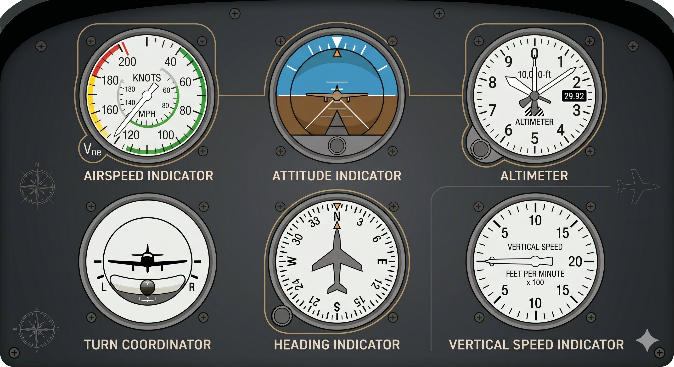
The airspeed indicator (ASI) measures the difference between pitot pressure — ram air entering the pitot tube from the relative wind — and static pressure (ambient atmospheric pressure from the static port). This pressure difference, called dynamic pressure, is proportional to airspeed. The ASI converts this pressure difference into a speed reading displayed in knots. Learn more about weather for pilots →
The four types of airspeed
Indicated Airspeed (IAS) is what the instrument displays — uncorrected for instrument error, position error, or atmospheric density. All published V-speeds in the POH are given as IAS. When your instructor says "fly 70 knots on final," they mean IAS.
Calibrated Airspeed (CAS) is IAS corrected for instrument and position error — the errors caused by the location of the pitot tube and static port on the airframe. In the normal operating speed range these corrections are small (typically 1–5 kts), but they can be significant near stall or at very high airspeeds. CAS tables are published in the POH.
True Airspeed (TAS) is CAS corrected for non-standard pressure and temperature — the actual speed of the aircraft through the air mass. TAS increases approximately 2% per 1,000 ft above sea level. At 10,000 ft, TAS is roughly 20% higher than IAS for the same flight conditions. TAS is used for E6B navigation calculations, filing IFR flight plans, and computing groundspeed with wind.
Groundspeed (GS) is TAS corrected for wind — the speed across the ground. Tailwind increases GS above TAS; headwind decreases it. GS is computed on the E6B and displayed by GPS, but is not shown on the ASI.
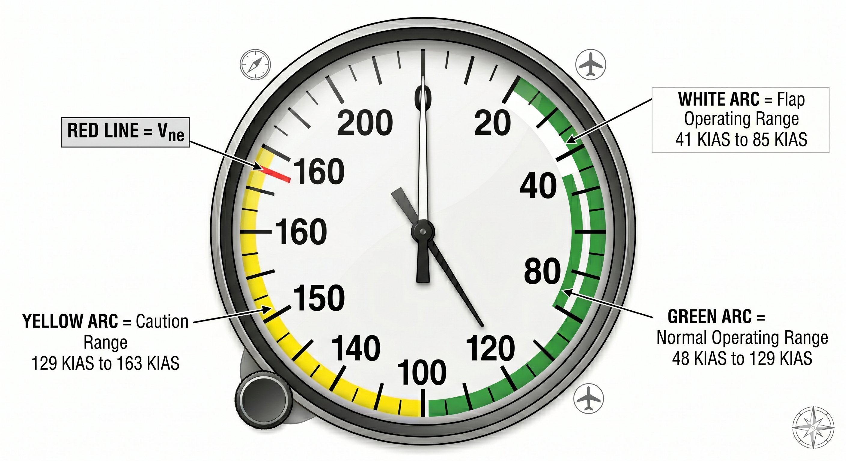
ASI colored arcs and V-speed markings
| Color/Mark | Speed range | Meaning |
|---|---|---|
| White arc | Vs0 to Vfe | Flap operating range. Bottom = Vs0 (power-off stall, landing config). Top = Vfe (max flap extended speed — structural limit). |
| Green arc | Vs1 to Vno | Normal operating range, flaps retracted. Bottom = Vs1 (clean stall). Top = Vno (max structural cruising speed). |
| Yellow arc | Vno to Vne | Caution range — smooth air only. Enter only if you are certain the air is completely smooth and undisturbed. |
| Red line | Vne | Never-exceed speed. Structural flutter or failure can occur above this speed. Exceed it never, under any circumstances. |
V-speed study tip for the oral exam: Your DPE will ask the V-speeds for your specific training aircraft. They are in the POH's Operating Limitations section (also sometimes called Section 2). Memorize them from your aircraft's POH — not generic values from a textbook. The numbers vary by aircraft serial number, weight, and configuration. See 14 CFR Part 23 for airworthiness standards that define what each speed designation means structurally.
Using airspeed in actual flying — what each color arc means operationally
The airspeed indicator's color coding isn't decoration — each arc and line tells you something operationally important about how to fly the aircraft right now:
White arc (Vso to Vfe): The flap operating range. You can extend flaps anywhere in the white arc. The bottom of the white arc is Vso — stall speed in the landing configuration (full flaps, gear down). The top is Vfe — maximum flap extension speed. Extending flaps above Vfe risks structural damage. In practice: get into the white arc (typically 80–100 knots in a C172) before extending flaps on approach. Below the white arc with flaps extended, you're dangerously close to stall.
Green arc (Vs1 to Vno): The normal operating range. Vs1 at the bottom is stall speed in the clean configuration (no flaps). Vno at the top is the maximum structural cruising speed — the speed above which you should not fly in rough or turbulent air. In smooth air, you can fly up to Vne (red line), but turbulence in the yellow arc risks structural damage.
Yellow arc (Vno to Vne): The caution range. Flight in the yellow arc is permissible only in smooth air. If you encounter turbulence here, slow to the green arc immediately.
Red line (Vne): Never Exceed speed. Structural failure is possible above this speed. No exceptions.
Blue line (on multi-engine aircraft): Vyse — best single-engine rate of climb speed. Not applicable to most training aircraft.
Indicated vs. true airspeed — and why it matters for navigation
The airspeed indicator measures indicated airspeed (IAS) — the dynamic pressure of the air hitting the pitot tube, converted to airspeed. At sea level on a standard day, IAS equals true airspeed (TAS). But as altitude increases and air density decreases, the same IAS corresponds to a higher actual speed through the air.
This matters for navigation: your ground speed (and therefore your flight time and fuel burn) depends on your true airspeed, not your indicated airspeed. A Cessna 172 indicating 110 knots at 8,000 feet is actually doing about 125 knots through the air (TAS). Use the E6B or the calculator in your EFB to convert IAS to TAS for cross-country flight planning. The rule of thumb: TAS increases approximately 2% per 1,000 feet of altitude above sea level.
Lesson 2 — The Altimeter and Density Altitude
The altimeter measures atmospheric (static) pressure and converts it to an altitude reading using the standard atmosphere relationship: pressure decreases approximately 1 inHg per 1,000 ft. Setting the current local altimeter setting in the Kollsman window tells the instrument what sea-level pressure is today, allowing it to display altitude above mean sea level (MSL) accurately.
Types of altitude — a critical distinction
Indicated altitude: What the altimeter displays with the current altimeter setting entered in the Kollsman window. This is what ATC references and what determines your altitude relative to other aircraft.
Pressure altitude: What the altimeter reads with 29.92 inHg set in the Kollsman window — altitude above the standard datum plane. Used for performance chart calculations and all flight at/above 18,000 ft MSL (Class A airspace), where all aircraft set 29.92 and report altitudes as Flight Levels.
Density altitude: Pressure altitude corrected for non-standard temperature. The altitude the aircraft's performance systems actually experience. This is the number that drives every performance chart calculation.
True altitude: Actual altitude above mean sea level, accounting for the difference between actual atmospheric pressure and standard. Needed for terrain clearance calculations; close to indicated altitude near sea level in standard conditions.
The pressure altimeter setting rule — §91.121
Under 14 CFR §91.121, the altimeter must be set to the current reported altimeter setting of the nearest station along the route when at or below 18,000 ft MSL. When no station is available within 100 nm, use the elevation of the departure or destination airport. Above 18,000 ft: set 29.92 inHg.
"High to low, look out below": Flying from high pressure to low pressure without updating the altimeter causes it to over-read — the instrument shows you higher than you actually are. A pilot maintaining "4,500 ft indicated" who has flown into a low pressure area without updating may be 300–400 ft lower than they believe. Near terrain or in mountainous areas this error is fatal. Always update the altimeter setting when receiving new ATIS, when ATC provides it, and when crossing into new area weather.
Density altitude — the performance killer
Density altitude is pressure altitude corrected for non-standard temperature. On a hot summer day at a high-elevation western airport, the combination of high field elevation and high temperature can produce density altitudes 3,000–5,000 ft above field elevation. Every POH performance chart — takeoff roll, climb rate, landing distance — is computed at standard conditions. At high density altitude, actual performance degrades dramatically from those charts.
Density altitude worked example:
Airport elevation: 4,500 ft MSL. Altimeter setting: 29.72 inHg. OAT: 95°F (35°C).
Step 1 — Pressure altitude: 4,500 + (29.92 − 29.72) × 1,000 = 4,500 + 200 = 4,700 ft PA
Step 2 — ISA temperature at 4,700 ft: 15°C − (4,700 × 2/1,000) = 15 − 9.4 = 5.6°C standard
Step 3 — ISA deviation: 35°C − 5.6°C = +29.4°C above standard
Step 4 — DA: 4,700 + (29.4 × 120) ≈ 4,700 + 3,528 ≈ 8,228 ft density altitude
The aircraft "feels" like it's at 8,228 ft while sitting on a 4,500 ft runway. Consult performance charts at 8,200 ft density altitude — not 4,500 ft.
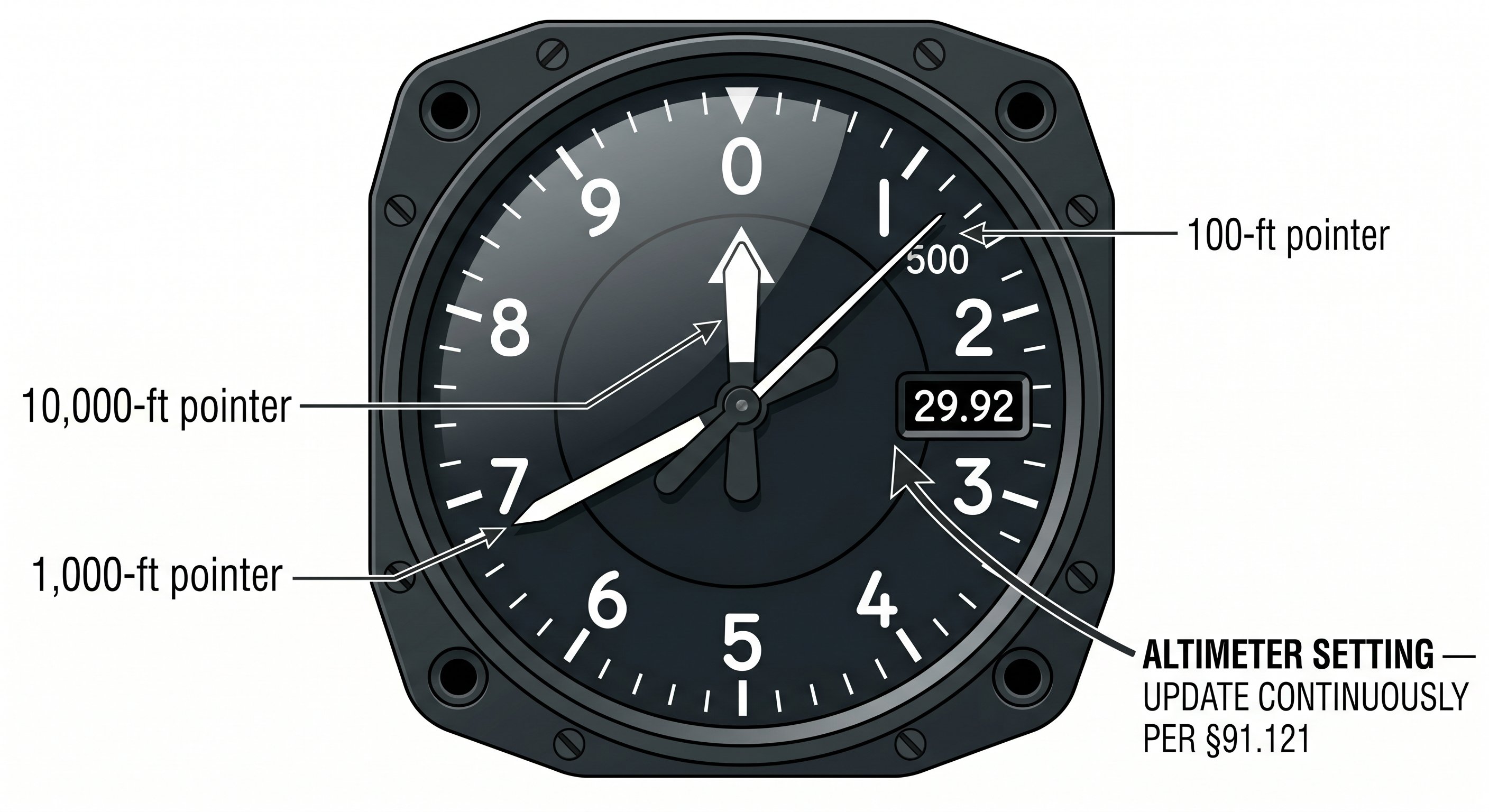
Setting the altimeter — when and why it matters
The altimeter measures atmospheric pressure and converts it to altitude based on the International Standard Atmosphere (ISA) pressure model. When you set the Kollsman window to the current local altimeter setting (QNH), the altimeter reads field elevation when you're on the ground at that airport — confirming it's set correctly. If your ground reading is off by more than 75 feet from field elevation, the altimeter should be flagged for maintenance before flight.
Update the altimeter setting whenever ATC provides a new one, and when transitioning between regions. Stale altimeter settings cause altitude errors: a 0.01 inHg error equals approximately 10 feet of altitude error. On a long cross-country, the pressure field can change significantly — always update from the most recent ATIS, AWOS, or ATC when available.
Density altitude — the real altitude your engine thinks it's at
Density altitude is one of the most practically important concepts in aviation — and one of the most frequently misunderstood. Density altitude is the pressure altitude corrected for non-standard temperature. It tells you what the air density is equivalent to in terms of altitude. This is what your engine, propeller, and wings are "seeing" in terms of air density.
High density altitude means: reduced engine power (less air for combustion), reduced propeller efficiency (blades bite less dense air), and reduced wing lift (same angle of attack produces less lift). All three combine to dramatically increase takeoff distance and reduce climb rate.
Salt Lake City (elevation 4,229 ft) on a hot summer afternoon (95°F) has a density altitude of approximately 7,500 feet. A Cessna 172 operating at "sea level" performance at 7,500 density altitude needs 40–60% more runway to take off than at sea level, and may be unable to clear nearby terrain that would be easily cleared on a standard day. Compute density altitude before every flight at high elevation airports and on hot days.
Lesson 3 — Vertical Speed Indicator
The vertical speed indicator (VSI) measures the rate of change of static pressure and converts it to a climb or descent rate in feet per minute. Because it measures rate of change rather than absolute pressure, the VSI has a characteristic lag of approximately 6–9 seconds — it shows sustained trends, not instantaneous readings. An instantaneous VSI (IVSI) uses accelerometers to reduce this lag and is found in some aircraft.
In normal flight, use the VSI as a trend indicator rather than an absolute reference. During cruise, a VSI pegged at zero confirms level flight. During approach, target approximately 400–700 fpm descent for a standard 3° glidepath — the exact value depends on groundspeed (descent rate = GS × 5.2 for 3° approaches; at 90 kts GS, that's 90 × 5.2 ≈ 468 fpm).
Using the VSI in practice — what it tells you that the altimeter doesn't
The vertical speed indicator shows rate of altitude change in feet per minute. The altimeter shows current altitude but requires mental math to determine rate of change. The VSI gives you immediate trend information — the moment you begin a climb or descent, the VSI responds (after its characteristic lag) and shows you whether your rate is increasing, stable, or decreasing.
In VFR cruise, most pilots target a specific VSI reading during climbs and descents. A 500 fpm climb in a Cessna 172 corresponds to approximately 80 knots at Vy with full power. During descent, 500 fpm at reduced power gives a stable, controllable approach gradient. The VSI tells you whether you're achieving your target rate without mental math from the altimeter.
The 6–9 second lag and how to work with it
The VSI has an inherent 6–9 second lag because it measures the rate at which pressure changes in a calibrated chamber — the chamber pressure takes time to equilibrate. This means: if you establish a climb right now, the VSI won't show the full climb rate for 6–9 seconds. If you change the climb rate, the VSI won't reflect the change for another 6–9 seconds.
The practical implication: don't chase the VSI. If you're trying to maintain 500 fpm and the VSI briefly shows 600, resist the urge to push forward immediately. The reading may already be reflecting a correction you've already made, just delayed. Instrument flying teaches patience with the VSI — scan it as a trend instrument, not a precise real-time indicator. Adjust attitude, wait for the response, then fine-tune.
In turbulence, the VSI is essentially useless — it swings violently with every gust. Focus on attitude in turbulence; the VSI averages out to something meaningful only in smooth air.
The VSI as a glidepath monitor on approach
One of the most practical uses of the VSI is monitoring your approach glidepath. A standard 3-degree ILS glidepath requires a specific descent rate that varies with your groundspeed. The formula: descent rate (fpm) = groundspeed (knots) × 5.2. At 90 knots groundspeed, a 3-degree approach requires roughly 470 fpm. At 80 knots, about 415 fpm. At 100 knots, about 520 fpm.
On a visual approach without a glideslope, target 400–500 fpm descent from pattern altitude to the threshold. If the VSI shows more than 700–800 fpm consistently, you are either too high and diving to catch up, or flying an excessively steep approach. Steep approaches create fast sink rates at the flare — often resulting in hard landings. Shallow approaches (VSI barely moving negative) mean you're going to land long. Let the VSI guide your power and pitch adjustments: nose up + power on to reduce descent rate; nose level + power reduce to increase it.
What the VSI does during different phases of flight
Immediately after takeoff: VSI climbs rapidly as the aircraft accelerates and establishes the climb. It doesn't settle to a steady value until the airspeed and pitch attitude stabilize — usually 20–30 seconds after liftoff. Don't be alarmed by initial fluctuations.
In cruise: VSI pegged at zero (or very close to it) confirms you've achieved level flight. Small positive or negative readings indicate the aircraft is still drifting. Adjust pitch slightly until the VSI stabilizes at zero — this is more reliable than chasing a slowly changing altimeter reading.
In turbulence: The VSI is nearly useless — it oscillates rapidly with every gust because the static pressure is fluctuating. In moderate turbulence, swings of ±500 fpm or more are common even in nearly level flight. Ignore the VSI in turbulence and focus on attitude.
When transitioning altitude: When climbing to a new cruise altitude, use the VSI to confirm you've stopped climbing. Set the target altitude on the altimeter, and when the VSI settles to zero, you've leveled off. The 6–9 second lag means the VSI will still show a slight positive reading for several seconds after you've actually reached level flight — be patient before over-correcting with nose-down input.
Blocked static port effect on the VSI
A blocked static port freezes the VSI at zero — permanently. If the static port ices over or is physically blocked, the VSI reads zero regardless of actual climb or descent. This is one of the reasons you cross-check instruments: if the altimeter is frozen and the VSI reads zero in what feels like a descent, suspect a blocked static port. Opening the alternate static source (if equipped) restores static airflow and brings the VSI back to life — with a brief transient as the pressure equalizes.
Lesson 4 — Attitude Indicator and Heading Indicator
The attitude indicator (AI, also called artificial horizon) and heading indicator (HI, also called directional gyro) are gyroscopic instruments that use the property of gyroscopic rigidity — a spinning mass resists changes to its axis of rotation — to maintain a fixed reference as the aircraft maneuvers.
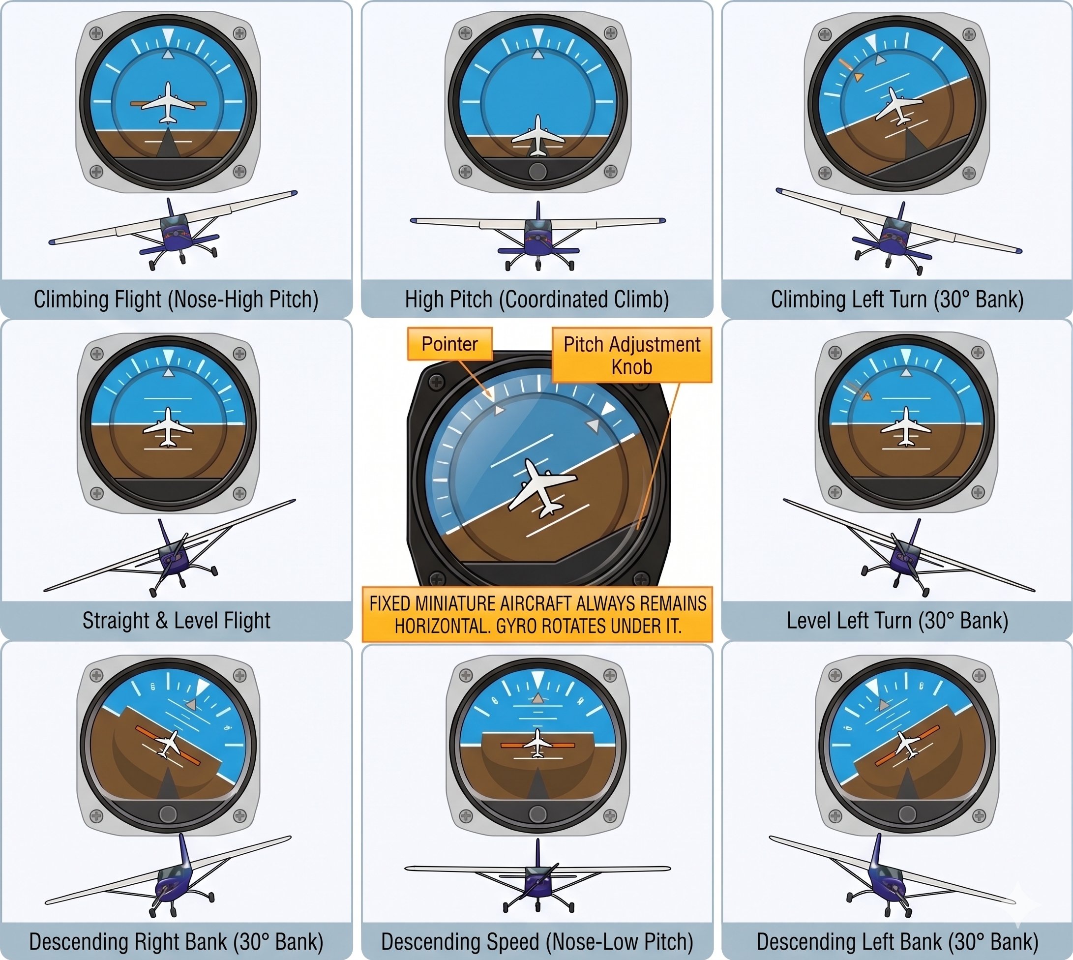
Attitude indicator — how to read it
The AI has two moving elements relative to the fixed miniature airplane: the artificial horizon line (where earth meets sky) and the bank angle indicator at the top. The miniature airplane is fixed to the instrument case — it represents your aircraft. The horizon card moves with the gyroscope. Bank angle is read from the degree markings at the top (typically 10, 20, 30, 45, 60°). Pitch is read from the horizon bar position — above center means nose high, below means nose low. The brown color conventionally represents earth; blue represents sky.
Heading indicator — use and limitations
The HI maintains heading reference through gyroscopic rigidity — it does not seek magnetic north. This means two things: it must be set to the magnetic compass before flight (and after any prolonged ground operation), and it drifts due to gyroscopic precession and Earth's rotation. Typical drift: 3–5° per 15 minutes. Per AIM guidance, realign the HI with the magnetic compass every 15 minutes in straight-and-level, unaccelerated flight. The HI is far more useful for turning (compass errors make the compass unreliable in turns) but requires the magnetic compass for initial and periodic calibration.
Vacuum failure — the insidious instrument failure: AI and HI gyros spool down over 3–5 minutes after vacuum loss, appearing functional initially before slowly diverging from reality. In IMC this is a deadly trap. Always monitor the suction gauge (green arc: 4.5–5.5 inHg). During vacuum failure: turn coordinator (electric), magnetic compass, ASI, altimeter, and VSI remain reliable. These five instruments are all you need for partial panel flight. See FAA Instrument Flying Handbook Ch. 6 for partial panel procedures.
Reading the attitude indicator correctly — the bank/pitch trap
Student pilots frequently misread the attitude indicator during unusual attitude recovery. The key to reading it correctly: the miniature airplane in the instrument represents your aircraft, and the horizon bar represents the actual horizon. If the miniature airplane is above the horizon bar, the nose is up. If the miniature airplane is banked left relative to the horizon bar, the aircraft is banked left.
The common error in steep banks: as the horizon bar tilts steeply (30° or more), students sometimes lose their visual reference and either apply incorrect correction or freeze. Practice: in a 45° left bank, the horizon bar runs diagonally — upper left to lower right. The miniature aircraft's wings are tilted right relative to the bar. To recover: level the miniature aircraft's wings relative to the bar, then correct pitch.
Heading indicator precession — when and how to realign
The heading indicator (HI) is a gyroscopic instrument that provides a stable heading reference free from the compass errors that plague the magnetic compass in turning flight. However, the gyro precesses over time — it slowly drifts away from its correct heading due to friction in the bearings and the rotation of the Earth. This drift can be 3–5 degrees per 15 minutes in some instruments.
The correct procedure: every 15 minutes during cruise, compare the HI to the magnetic compass (when the aircraft is in straight, level, unaccelerated flight — the only time the compass is reliable). Align the HI to the compass if there's a discrepancy of more than a degree or two. Some modern aircraft use an HSI (Horizontal Situation Indicator) slaved to a remote compass or magnetometer, which eliminates this manual realignment requirement.
A common student error: realigning the HI while in a turn or just after stopping a turn. The compass is unreliable in those conditions (acceleration/deceleration error, northerly/southerly turning error). Always stabilize in straight and level flight before using the compass as a reference for HI alignment.
Unusual attitude recovery using the attitude indicator
An unusual attitude is any pitch or bank attitude significantly outside normal flight — nose high with decaying airspeed, nose low with accelerating airspeed, or steep bank in either direction, or any combination. Unusual attitude recovery is a required maneuver on the instrument rating practical test, but private pilots need the same skill because it's the immediate response to unexpected IMC entry or spatial disorientation.
Nose high unusual attitude recovery: (1) Increase power to full. (2) Lower the nose — reference the AI. (3) Level the wings with coordinated aileron and rudder. In a nose-high attitude, the priority is preventing a stall. Power first, then pitch down, then wings level.
Nose low unusual attitude recovery: (1) Reduce power to prevent further acceleration. (2) Level the wings first — bank increases load factor and stall speed. (3) Raise the nose to level flight. In a nose-low attitude, pulling back before leveling the wings increases load factor and can cause structural failure or an accelerated stall. Wings level first, then pull.
Heading indicator in cross-country navigation
In cross-country flight, the heading indicator is your primary heading reference — far more stable and easier to read than the magnetic compass. The workflow: compute your magnetic heading from the flight plan (true heading ± variation ± deviation = compass heading), dial it into the heading indicator after aligning to the compass on the ground, then fly the HI heading during cruise. Every 15 minutes in cruise, briefly check the magnetic compass (in straight, unaccelerated flight) and realign the HI if it has drifted.
A common student mistake: setting the HI to the runway heading before takeoff and forgetting to align it to the magnetic compass. Wind, taxiway turns, and the lack of gyro stabilization on the ground can cause the HI to drift significantly before you even take off. Always align HI to compass during the runup — in straight, level, engine-running conditions.
Gyro caging and erection — the first few minutes of flight
After engine start, gyroscopic instruments need time to spin up to operating speed and erect to their correct orientation. During this warmup period — typically 3–5 minutes — the AI and HI may show slightly erroneous readings. The AI may show a slight bank or pitch error; the HI may slowly drift to its correct heading as the gyro erects. Do not attempt to align the HI until the gyros have fully spun up. If you check the HI immediately after start and find it 15 degrees off the taxiway heading — wait. It may self-correct as the gyro reaches operating speed.
Lesson 5 — The Magnetic Compass and Its Errors
The magnetic compass is the original navigation instrument and the ultimate backup — no electrical, vacuum, or other aircraft power required. A magnetized needle floats in compass fluid, aligning with Earth's magnetic field. Despite its simplicity, it has two significant, predictable error categories that make it unreliable as a primary instrument during turns and during acceleration or deceleration on certain headings.
Why the compass has errors — magnetic dip
Earth's magnetic field lines are not horizontal at the surface — they dip into the Earth, increasingly so at higher latitudes. The compass card assembly is designed to pivot horizontally but is slightly weighted to counteract this dip. This counterweight creates the error source: when acceleration or bank tilts the compass assembly, the weighting causes the compass to respond as if to a false turn.
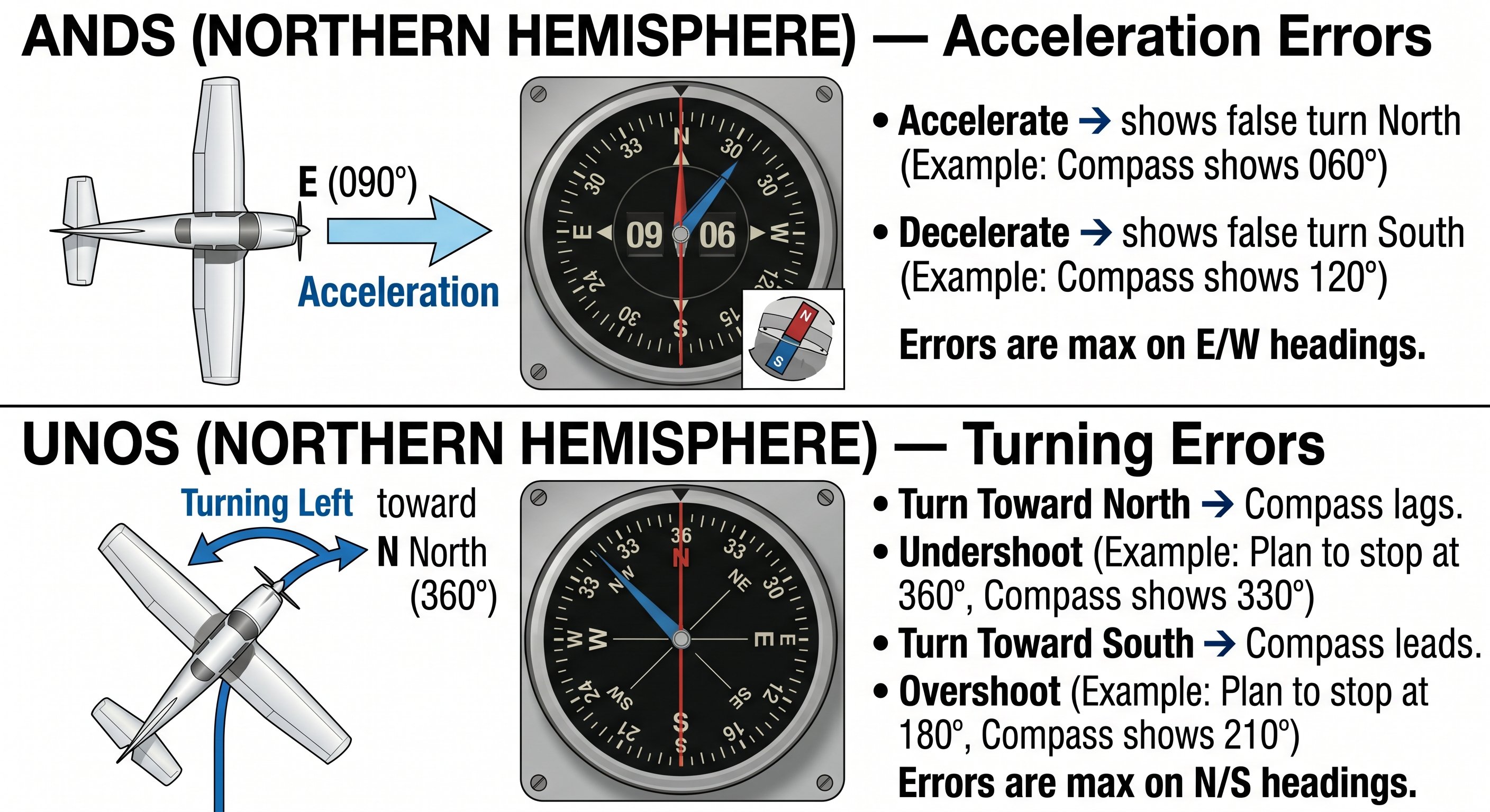
ANDS — Acceleration/Deceleration Errors
Accelerate North, Decelerate South — in the Northern Hemisphere, when on an easterly or westerly heading: accelerating causes the compass to indicate a turn toward North; decelerating causes it to indicate a turn toward South. There is no acceleration error when accelerating on northerly or southerly headings. These errors are temporary — the compass returns to the correct reading as acceleration ends.
UNOS — Turning Errors
Undershoot North, Overshoot South — when turning to a northerly heading, the compass lags; roll out earlier than the target heading. When turning to a southerly heading, the compass leads; roll out later. The amount to compensate equals approximately your latitude. At 35° N latitude: undershoot/overshoot by approximately 35°. Turning errors are minimal on east and west headings. Use the HI for all turns and verify with the magnetic compass only in straight-and-level unaccelerated flight.
Compass correction card: Each aircraft also has deviation — a small error caused by the aircraft's own magnetic field (from the engine, wiring, avionics). This error is different on each heading and each aircraft. The compass correction card, mounted near the compass, shows the deviation correction for various headings. Use it when flying with only the compass for reference. Deviation is different from variation (covered in Module 6).
Compass errors in practice — how to actually use the compass to navigate
The magnetic compass is the only navigation instrument that requires no electrical power and no vacuum — it works purely on Earth's magnetic field. But it has errors that make it unreliable in many common flight situations:
Variation (magnetic vs. true north): Magnetic north and true north are not the same location. The difference, called variation, depends on where you are on Earth and changes over time. Variation is shown by isogonic lines on sectional charts. East of the agonic line (0 variation), variation is west — subtract west variation from true course to get magnetic course. West of the agonic line, variation is east — add east variation. The mnemonic: "East is least, West is best" (when converting from true to magnetic: east variation = subtract, west variation = add).
Acceleration/deceleration error: On east or west headings, accelerating causes the compass to show a turn toward north. Decelerating causes it to show a turn toward south. The mnemonic: ANDS — Accelerate North, Decelerate South. This error only occurs on headings close to east or west — it's minimal on north or south headings.
Northerly/southerly turning error: When turning through north or south headings, the compass lags (north) or leads (south). Turning through north: the compass initially shows a turn in the wrong direction. To roll out on north in the northern hemisphere, stop the turn approximately 30° early (roll out when the compass shows approximately 330° if turning to north). Turning through south: the compass moves faster than the actual turn. Roll out approximately 30° late. The mnemonic: OSUN — Overshoot South, Undershoot North.
Using the compass for timed turns when the HI fails
If the heading indicator fails in flight, you can navigate using the magnetic compass — but you need to account for its turning errors. The practical technique: use the turn coordinator to maintain a standard rate turn (2-minute 360), and time the turn rather than reading the compass heading mid-turn. For a standard rate turn, 3 degrees per second means a 90-degree turn takes exactly 30 seconds. A 180-degree turn takes 60 seconds. Time it rather than watching the compass.
For rolling out on a specific heading using the compass only, apply the OSUN correction. Rolling out on North: roll out when the compass reads approximately 30° before reaching North (e.g., roll out at 330°N when turning to 360°). Rolling out on South: roll out when the compass reads approximately 30° past South (e.g., roll out at 210° when turning to 180°). East and West headings have much smaller errors — roll out approximately when the compass reads the target heading.
Magnetic deviation — what the compass correction card is for
In addition to variation (the difference between magnetic and true north), the compass also has deviation — errors caused by the magnetic fields of the aircraft's own electrical equipment, steel structure, and electronics. Deviation varies depending on the aircraft's heading. A compass calibration procedure called "swinging the compass" measures deviation on multiple headings and produces a compass correction card — the small placard mounted near the compass in every certified aircraft.
The compass correction card shows: for each magnetic heading you want to fly, what the compass should read to achieve that. For example, if you want to fly a magnetic heading of 270°, the card might say "steer 272°" because the aircraft's own magnetic field causes a 2° easterly deviation on that heading. Always check the compass correction card when navigating by compass — deviation errors of 5–10° are not uncommon in aircraft with lots of avionics.
Lesson 6 — Turn Coordinator and the Inclinometer
The turn coordinator uses a gyroscope tilted approximately 30° from the vertical axis, making it sensitive to both roll rate and yaw rate simultaneously. The miniature aircraft on the instrument face indicates rate of turn — not bank angle. This is a common misconception: the turn coordinator does not show bank angle; it shows how fast the aircraft is turning.
Standard rate turn
When the miniature aircraft's wingtip aligns with the turn index (the L or R tick mark), the aircraft is at standard rate — exactly 3° per second. At 3°/sec, a complete 360° turn takes exactly 2 minutes. Standard rate is used for instrument procedures, ATC-assigned turns, and as the basis for timing turns.
Bank angle formula for standard rate: Bank angle ≈ (TAS ÷ 10) + 5. At 90 kts TAS: (90 ÷ 10) + 5 = 14°. At 120 kts TAS: (120 ÷ 10) + 5 = 17°. At 180 kts: 23°. Useful for setting up standard rate turns without relying on the turn coordinator alone.
The inclinometer (ball) — coordination reference
The inclinometer beneath the turn needle — a black ball in a curved fluid-filled tube — shows coordination. In coordinated flight, gravity (pulling down) and centrifugal force (pulling outward in a turn) combine to keep the ball centered. When the ball moves:
- Ball to the left (skid): Too much rudder in the direction of turn — reduce rudder pressure on the turn side, or add opposite rudder.
- Ball to the right (slip): Insufficient rudder in the direction of turn — add more rudder pressure on the turn side.
The mnemonic "step on the ball" — press the rudder pedal on the same side as the ball displacement — always corrects coordination regardless of which direction the ball has moved.
Standard rate turns — why 2 minutes and how to fly them
A standard rate turn (Rate 1) completes a 360° turn in exactly 2 minutes — 3 degrees per second. ATC sometimes requests standard rate turns, and IFR procedures assume standard rate. The turn coordinator shows standard rate with the miniature aircraft's wing aligned with the tick mark on the instrument face.
The bank angle required for standard rate varies with airspeed: the faster you fly, the more bank is needed. A useful approximation: standard rate bank angle = (TAS ÷ 10) + 5. At 100 knots TAS, standard rate requires approximately 15° of bank. At 150 knots, approximately 20°. At cruise altitudes in faster aircraft, standard rate may require 25–30° of bank.
Slips and skids — reading the ball and applying correct rudder
The inclinometer ball shows whether the aircraft is in coordinated flight, a slip, or a skid:
Ball centered: Coordinated flight. The rudder input matches the bank angle. This is the normal condition for all turns.
Ball displaced toward the low wing (inside the turn): A slip. The aircraft is slipping toward the inside of the turn — the bank angle is too steep for the rudder input, or there's too much opposite rudder. Apply rudder toward the ball (into the turn) to correct. A slip is sometimes intentional: forward slips and side slips use this condition deliberately to increase drag and descend more steeply without increasing airspeed.
Ball displaced toward the high wing (outside the turn): A skid. The aircraft is skidding to the outside of the turn — the nose is yawing faster than the bank indicates, typically from too much inside (bottom) rudder. A skid is particularly dangerous in the base-to-final turn at low altitude: a right-rudder skid in a left turn creates differential angle of attack across the wings (the inside wing has higher AoA) that can lead to an accelerated stall on the low wing. Step on the ball — add rudder pressure in the direction of ball displacement — to correct.
Recognizing and correcting a skid at low altitude
The most dangerous application of ball/rudder awareness happens on the base-to-final turn at low altitude. Here's the scenario: you're turning from base leg to final approach, and you've overshot the centerline. The instinctive response is to steepen the bank and add inside (bottom) rudder to tighten the turn. The result is a skid — the ball moves to the high side (outside the turn). In a skid, the inside wing has a higher angle of attack than the outside wing. If AoA exceeds the critical value on that inside wing, it stalls first and rolls rapidly toward the ground — a stall/spin entry at 400 feet AGL with no altitude for recovery.
The correct response to an overshot final: go around. Never tighten the turn with bottom rudder at low altitude. If you must continue the turn, steepen the bank slightly (which increases load factor — be aware of this) and do not add bottom rudder. Keep the ball centered. If you can't make the centerline without using bottom rudder in the turn, go around and re-enter the pattern.
Intentional slips — when an out-of-balance ball is exactly right
A forward slip is an intentional uncoordinated maneuver used to increase drag and descent rate without increasing airspeed — useful when you're too high on final and need to lose altitude quickly without extending flaps (if flaps are inoperative or the approach calls for no-flap landing).
In a forward slip: apply full opposite rudder while simultaneously banking into the slip. For example, right aileron (right bank) with left rudder. The aircraft is now flying sideways through the air — the fuselage is exposed to the relative wind, creating significant additional drag. The ball will be displaced toward the low wing (inside the bank). The airspeed indicator may read slightly erroneously during a slip because the pitot tube is no longer aligned with the relative wind. When ready to end the slip: reduce rudder and aileron simultaneously and resume coordinated flight.
Lesson 7 — Required Instruments and Equipment
Under 14 CFR §91.205, specific instruments are required for different types of flight. The mnemonic ATOMATOFLAMES is commonly used for VFR day requirements, and GRABCARD for additional night VFR requirements.
| Mnemonic | Instrument/Equipment | FAR Reference |
|---|---|---|
| VFR DAY — ATOMATOFLAMES (§91.205(b)) | ||
| A | Airspeed indicator | §91.205(b)(1) |
| T | Tachometer (for each engine) | §91.205(b)(2) |
| O | Oil pressure gauge | §91.205(b)(3) |
| M | Manifold pressure gauge (if applicable) | §91.205(b)(4) |
| A | Altimeter | §91.205(b)(5) |
| T | Temperature gauge (liquid-cooled engines) | §91.205(b)(6) |
| O | Oil temperature gauge | §91.205(b)(7) |
| F | Fuel gauge (each tank) | §91.205(b)(8) |
| L | Landing gear position indicator (retractable) | §91.205(b)(9) |
| A | Anti-collision light system | §91.205(b)(11) |
| M | Magnetic direction indicator (compass) | §91.205(b)(12) |
| E | ELT | §91.207 |
| S | Safety belts / harnesses | §91.205(b)(10) |
| NIGHT ADD-ONS — GRABCARD (§91.205(c)) | ||
| G | Generator or alternator | §91.205(c)(1) |
| R | Radio (two-way communication and navigation) | §91.205(c)(2) |
| A | Airspeed indicator (already required) | — |
| B | Ball (inclinometer) | §91.205(c)(3) |
| C | Clock (with sweep seconds or digital display) | §91.205(c)(4) |
| A | Attitude indicator | §91.205(c)(5) |
| R | Rate-of-turn indicator (turn coordinator or turn-and-slip) | §91.205(c)(6) |
| D | Directional gyro (heading indicator) | §91.205(c)(7) |
- ASI arcs: White (Vs0–Vfe, flap range) · Green (Vs1–Vno, normal ops) · Yellow (caution, smooth air only) · Red line (Vne, structural limit).
- IAS: instrument reading. TAS: actual speed through air (~+2%/1,000 ft). GS: TAS ± wind. Use IAS for flying; TAS for navigation planning.
- Density altitude = pressure altitude corrected for non-standard temperature. Always compute performance from DA, not field elevation. Hot + high = very high DA.
- "High to low, look out below" — flying into lower pressure without updating the altimeter causes over-reading. Required by §91.121 to update altimeter setting continuously.
- AI and HI are vacuum-powered in conventional aircraft. Gyroscopic rigidity maintains attitude/heading reference. HI drifts — realign with compass every 15 minutes in straight-and-level flight.
- Vacuum failure: AI and HI spool down gradually — insidious in IMC. Turn coordinator (electric), compass, and pitot-static instruments remain. Monitor suction gauge continuously.
- Compass ANDS on east/west headings: Accelerate North, Decelerate South. Compass UNOS on N/S turns: Undershoot North, Overshoot South.
- Standard rate turn = 3°/sec = 360° in 2 minutes. Formula: bank angle ≈ (TAS ÷ 10) + 5.
- Ball = coordination. "Step on the ball." ATOMATOFLAMES = VFR day required. GRABCARD = additional night VFR required. Both per §91.205.
Why each required instrument is on the list — the safety logic
The ATOMATOFLAMES list isn't arbitrary — each instrument was added because its absence has caused accidents. Understanding the safety rationale helps you remember the list and understand what to do if one fails:
Airspeed indicator: Without it, you cannot ensure you're above stall speed or below Vne. It's the primary speed reference for every phase of flight.
Altimeter: Required for terrain clearance and airspace compliance. Without it, you cannot verify you're above obstructions or comply with altitude clearances.
Magnetic direction indicator (compass): Navigation. It's the only heading instrument that works without electrical power or vacuum — the ultimate backup.
Tachometer: Monitors engine speed. Over-revving damages engines. Under-revving may indicate a problem. The tachometer is also how time is tracked for engine maintenance intervals.
Oil pressure gauge: Low oil pressure is an immediate engine emergency. Loss of oil pressure means bearing failure is seconds to minutes away — land immediately.
Fuel quantity gauge: Required for each tank. Fuel exhaustion (the pilot ran out of fuel) is one of the leading causes of engine failures — entirely preventable with proper fuel monitoring and pre-flight planning.
Anti-collision lights (VFR day): Make the aircraft visible to other traffic. Required during day VFR operations since 1996.
ELT — the emergency locator transmitter
While not part of the ATOMATOFLAMES mnemonic, the ELT (Emergency Locator Transmitter) is required under FAR 91.207 for most aircraft operating in the US. The ELT activates automatically upon impact (G-force trigger) or can be manually activated. Modern 406 MHz ELTs transmit on both 406 MHz (satellite detection) and 121.5 MHz (guard frequency). The 121.5 MHz signal is monitored by most commercial aircraft and ATC; the 406 MHz signal goes to COSPAS-SARSAT search and rescue satellites and can pinpoint the ELT's location within a few kilometers within minutes of activation.
ELTs must be inspected every 12 months, and the battery must be replaced or recharged after 1 hour of cumulative use or when 50% of its useful life has expired. Check the ELT battery expiration date during preflight — it's typically placarded on or near the ELT unit.
Operating with inoperative instruments — MEL and KOEL
Not every inoperative instrument grounds the aircraft. If the aircraft has a Minimum Equipment List (MEL) approved by the FAA, the MEL specifies which instruments can be inoperative under what conditions. Without an MEL, the aircraft must comply with the Kind of Operations Equipment List (KOEL) in the POH, and all required instruments for the intended operation must be functional.
The practical rule for student pilots: if a required instrument is inoperative, do not fly until it's repaired (or properly deactivated and placarded per FAR 91.213). An inoperative fuel gauge is a required-instrument problem. An inoperative EFB (electronic flight bag) is not a required instrument problem — it's a convenience device. Know which category each piece of equipment falls into before flight.