Airports and Airspace — Owning Your Place in the NAS
The National Airspace System is a layered structure — each class with specific entry requirements, weather minimums, and operating rules. Add airport signs, runway markings, and airport lighting, and you have an entire language pilots must read correctly every time they fly. This module covers every airspace class, every required sign and marking, runway and taxiway lighting systems, and the light gun signals you must know if your radio fails.
- State entry requirements and VFR weather minimums for all six airspace classes
- Describe the Mode C veil and when a transponder/ADS-B is required
- Identify every airport surface sign by color and describe what it means
- Describe runway and taxiway markings — centerlines, hold-short lines, displaced thresholds
- Explain runway and taxiway lighting systems including PAPI, VASI, and REIL
- Describe the types of special use airspace and which require prior authorization
- Recall all light gun signals for both airborne and ground-based aircraft
Lesson 1 — Airspace Overview and Class A
The US National Airspace System divides airspace into classes identified by letters A through G. Each class balances the needs of IFR traffic, VFR traffic, and ground operations below. Understanding the system begins with recognizing that airspace classes exist for a reason — each reflects the density and type of traffic that uses it and the level of ATC service appropriate for those operations.
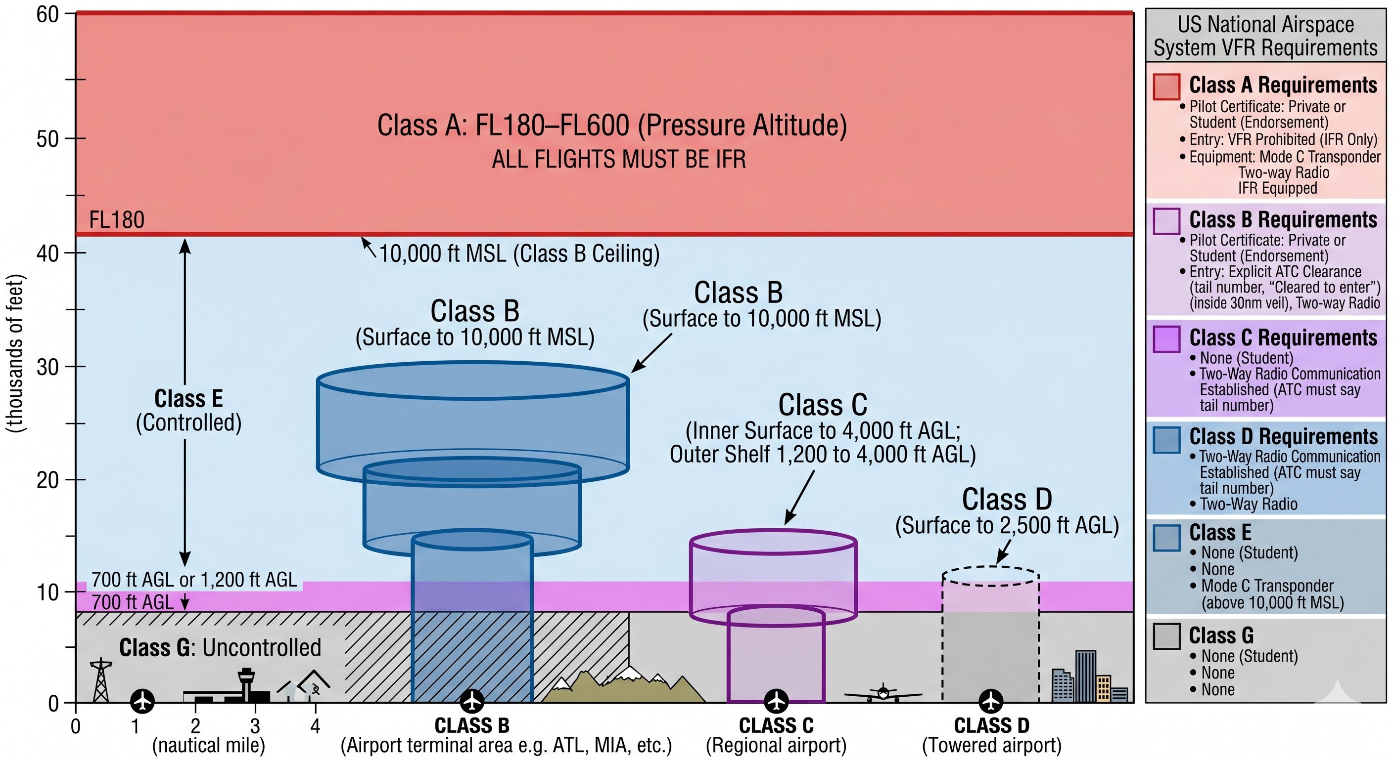
Class A airspace covers the entire continental US from 18,000 ft MSL to 60,000 ft MSL. All flight in Class A is conducted under IFR — VFR flight is prohibited. Per 14 CFR §91.135, an IFR clearance, instrument-rated pilot, and properly equipped aircraft are all required. Altimeters are set to 29.92 inHg; altitudes reported as Flight Levels (FL180, FL250, FL410). For private pilots, Class A is a ceiling — you operate below it.
How to think about the airspace system — the underlying logic
The FAA designed the airspace system around a simple principle: the more traffic, the more control. Airspace classes form a spectrum from fully controlled (Class A, mandatory IFR, ATC separation for everyone) to completely uncontrolled (Class G, no ATC contact required, no separation services). The class letter tells you what you need to enter and what services you receive.
Think of it this way: Class A is the interstate highway system — high speed, mandatory lanes, ATC knows exactly where everyone is. Class G is a dirt road in the countryside — you share the road with whoever else is there, look out for yourself, and nobody is directing traffic. Everything in between blends these approaches based on traffic density and proximity to airports.
Class A — what it means for VFR pilots
Class A airspace exists from 18,000 feet MSL (FL180) to 60,000 feet MSL (FL600) inclusive. All operations in Class A require an IFR clearance — VFR flight is not permitted. You must fly on an instrument flight plan, be in radio contact with ATC, and fly IFR altitudes (flight levels).
For private pilot students, Class A matters in two ways: (1) you need to know it exists and that you cannot enter it VFR, and (2) understanding why it exists helps you understand the whole system. At altitudes above 18,000 feet, airspeeds and traffic densities make see-and-avoid completely impractical. ATC radar separation is the only viable solution, so everyone in Class A is IFR and under positive control.
The practical boundary: if you are climbing VFR and reach 17,999 feet MSL — stop. Do not enter Class A. The transition altitude between Class E (where VFR is permitted) and Class A is 18,000 feet MSL. In practice, most light training aircraft cruise well below this altitude, but mountain flying in the western US sometimes brings VFR flights close to this limit on high-terrain crossings.
Reading airspace on the sectional chart
Each airspace class has a specific depiction on VFR sectional charts. Before flying in any area, identify every airspace class present along your route and within a reasonable radius:
- Class B: Solid blue lines. Multiple rings (layers) show the floor and ceiling of each segment. The innermost ring typically extends from the surface to the ceiling altitude.
- Class C: Magenta (dark pink) solid lines with two rings — the 5 nm inner circle and the 10 nm outer ring.
- Class D: Blue dashed lines. Single ring around the primary airport.
- Class E surface: Magenta dashed lines. Class E extends to the surface (for instrument approaches).
- Class E at 700 ft AGL: Magenta shading (fuzzy edge, like a shadow). Class E begins at 700 ft AGL in this area.
- Class E at 1,200 ft AGL: No marking needed — this is the default almost everywhere in the US.
- Class G: Not explicitly shown — it's whatever isn't Class E or controlled airspace.
Lesson 2 — Class B Airspace
Class B surrounds the nation's busiest airports — approximately 37 locations including Atlanta, Chicago O'Hare, Los Angeles, and Dallas/Fort Worth. The shape is an inverted wedding cake: a series of cylinders at increasing altitudes and radii extending from the surface up to 10,000 ft MSL, designed to accommodate the instrument approach and departure corridors of the primary airport.
Entry requirements — §91.131
- ATC clearance with specific language. The controller must use the words "cleared into Class Bravo airspace" or equivalent. "Squawk 4532" alone is not a clearance. "Fly heading 250" is not a clearance. Only the Bravo clearance wording authorizes entry.
- Mode C transponder (altitude-encoding) within Class B and within the 30 nm Mode C veil.
- ADS-B Out — required in Class B and within 30 nm veil per §91.225.
- Private Pilot certificate or higher. Student pilots may enter with a specific CFI endorsement for that exact Class B airport, not a blanket student endorsement.
VFR weather minimums in Class B: 3 statute miles visibility and clear of clouds. The "clear of clouds" standard — rather than the standard cloud clearance distances — reflects the ATC separation provided to all traffic within Class B. Pilots maintain visual separation from other VFR traffic; ATC maintains IFR separation.
Navigating Class B in practice — what actually happens
Class B is the airspace where the most mistakes happen, because the requirements are strict and the consequences of an unauthorized entry are severe. Here is exactly what you need to enter Class B:
- ATC clearance: Not just communication — actual clearance. You must hear the words "Cleared into Class Bravo airspace" (or "Cleared through the Bravo"). Being told to "stand by" or getting a traffic advisory is not a clearance. If you're not explicitly cleared, you are not authorized to enter.
- Mode C transponder and ADS-B Out: A working Mode C transponder is required at and within 30 nm of Class B primary airports (the Mode C veil). ADS-B Out is required in Class B and within 30 nm of Class B primary airports above 10,000 ft MSL.
- Two-way radio: Required to communicate with approach/departure control.
- For student pilots: Additional instructor endorsement is required to operate at certain specific Class B airports — not just any Class B. The FAA identifies a list of Class B airports (including the busiest like LAX, ORD, JFK) where student pilot solo operations require a specific endorsement in the logbook.
Flying below or around Class B — the VFR corridor approach
If you need to transit an area near a Class B airport but don't want to contact Approach Control or enter the Bravo, you have options:
Under the floor: Class B has multiple layers. The outer rings often have floors at 3,000 or 5,000 ft AGL — if you fly below the floor of the nearest segment, you're not in Class B and no clearance is needed. Check the sectional carefully for the exact floor altitude of each segment along your route.
VFR flyway: The FAA publishes VFR Terminal Area Charts (TAC) for Class B airports. These charts include published VFR flyways — suggested routes at specific altitudes that route VFR traffic around or under the Bravo without entering it.
Lateral avoidance: If it's impractical to fly under or through, simply route around the Class B laterally. Stay outside the outermost ring. The charted airspace is hard boundaries — outside is outside.
The key mindset: Class B is not a barrier to general aviation. Approach Control is generally happy to work with VFR aircraft requesting Bravo clearances. But if you're not sure of the requirements, flying around or below is always an option.
LAHSO — Land and Hold Short Operations
At major Class B airports, ATC may issue a "Land and Hold Short" clearance — you're cleared to land on a runway but must stop before a specific intersection with another runway or taxiway. LAHSO requires: dry runway, an aircraft that can stop within the LAHSO distance (published in Chart Supplement), and your concurrence. You are never required to accept a LAHSO clearance. If you're not comfortable that you can stop in time, say "Unable LAHSO" and ATC will sequence you differently. LAHSO clearances are common at busy Class B airports with parallel runways.
Lesson 3 — Class C and D Airspace
Class C — major regional airports
Class C surrounds airports with an operating radar approach control (TRACON). The typical structure: a 5 nm inner circle from the surface to 4,000 ft AGL, and a 10 nm outer ring from 1,200 ft AGL to 4,000 ft AGL. Some Class C airports have a non-standard configuration — always check the sectional chart for the specific airport.
Entry requirement: Two-way radio communications established — the controller must acknowledge your call sign. Per AIM §3-2-4c: if the controller says "N12345, standby," your call sign was used — communications are established and you may proceed. If the controller says "all aircraft standby," your call sign was not used — do not enter. Mode C transponder and ADS-B Out are required. No minimum pilot certification — student pilots may enter Class C.
VFR weather minimums: 3 SM visibility, 500 ft below / 1,000 ft above / 2,000 ft horizontal from clouds.
Class D — towered airports
Class D surrounds airports with an operating control tower. Typical dimensions: 4–5 nm radius from the surface to approximately 2,500 ft AGL above the airport elevation. When the tower is not operating (tower hours are published in the Chart Supplement), Class D reverts to Class E or G — check the Chart Supplement and NOTAMs for tower hours.
Entry requirement per §91.129: Establish two-way radio communications with the tower before entering. No explicit clearance needed — contact alone suffices. No minimum pilot certification. ADS-B Out not required specifically for Class D (but is required elsewhere).
VFR weather minimums: 3 SM visibility, 500 ft below / 1,000 ft above / 2,000 ft horizontal from clouds.
Class C — the two-way communications requirement in depth
The key entry requirement for Class C is two-way radio communication established with ATC — not an explicit clearance, but actual contact. The distinction matters: if you call Approach and they respond with "N12345, standby" — contact has been established. You may enter the Class C. If they say nothing and don't acknowledge you — contact has not been established and you cannot enter until they respond.
This is different from Class B (which requires explicit clearance) and different from Class D (where the requirement is similar to Class C but at a local tower level). The two-way requirement reflects the traffic density: Class C airports have approach control radar and need to know you're there, but the traffic level doesn't require the positive clearance system of Class B.
Arriving at a Class C airport — the full radio sequence
When approaching a Class C airport from outside, here's the typical radio sequence:
- Get ATIS first, before any other contact. Note the information letter (Alpha, Bravo, etc.) and weather.
- Call Approach Control with your full call sign, position, altitude, and intentions: "Salt Lake Approach, Cessna November One Two Three Four Five, ten miles south at five thousand five hundred, inbound for landing, information Charlie."
- Approach responds, may give a squawk code, radar vectors, or traffic advisories. Follow their instructions.
- Approach will hand you off to Tower as you near the airport: "Contact Salt Lake Tower, 119.3."
- Call Tower with position and intention: "Salt Lake Tower, Cessna 12345, five mile final, runway 16R."
- Tower issues landing clearance. Read it back. Land.
- After landing, Tower hands you to Ground for taxi.
Class D — the tower relationship
Class D surrounds airports with an operating control tower but without approach radar — typically smaller regional airports. The floor is the surface; the ceiling is typically 2,500 ft AGL. The standard Class D is a 4–5 nm radius circle, though the actual size varies and is shown on the sectional.
Critical point: Class D only exists when the tower is operating. When the tower closes (after hours or on certain days at part-time towers), the Class D airspace reverts to Class E or Class G — no tower contact required, no two-way communication required to enter. Check the Chart Supplement for tower hours before assuming you need to call. Flying into what you think is Class D at night without calling the (closed) tower is fine — but flying into an active Class D without calling is a violation.
Communications at Class D are simpler than Class C — you talk directly to the Tower (no Approach Control). Call Tower when you're approximately 10 miles out with your position, altitude, and request.
Lesson 4 — Class E and G Airspace
Class E is the most pervasive airspace — it covers the vast majority of the continental US above 1,200 ft AGL, and begins at 700 ft AGL in areas surrounding airports with instrument approaches (depicted as magenta shading on sectional charts). No entry requirements. VFR pilots fly in Class E freely; ATC provides IFR separation to IFR traffic but has no authority over VFR flights beyond traffic advisories when requested.
| Airspace | Entry requirement | VFR vis | Cloud clearance | FAR |
|---|---|---|---|---|
| Class A | IFR clearance, IR required | N/A — IFR only | N/A | §91.135 |
| Class B | ATC clearance + Mode C + PPL | 3 SM | Clear of clouds | §91.131 |
| Class C | Two-way comms + Mode C | 3 SM | 500/1,000/2,000 | §91.130 |
| Class D | Two-way comms | 3 SM | 500/1,000/2,000 | §91.129 |
| Class E (below 10k) | None | 3 SM | 500/1,000/2,000 | §91.155 |
| Class E (at/above 10k) | None | 5 SM | 1,000/1,000/1 mile | §91.155 |
| Class G day (below 1,200 AGL) | None | 1 SM | Clear of clouds | §91.155 |
| Class G night (below 1,200 AGL) | None | 3 SM | 500/1,000/2,000 | §91.155 |
Why Class E exists at 700 ft AGL around many airports
When an airport has instrument approaches but no control tower, there's still a need to protect IFR aircraft as they transition between the instrument environment and visual flight near the ground. The Class E extension to 700 ft AGL (shown as magenta shading on sectionals) creates a buffer zone where IFR weather minimums apply rather than the more permissive Class G minimums. This protects instrument-approach aircraft from VFR traffic that might be operating legally in Class G with only 1 mile visibility and clear of clouds.
The practical impact: if you're flying VFR in an area with magenta shading and your altitude is between 700 ft and 1,200 ft AGL, you're in Class E — and you need 3 SM visibility and 500/1,000/2,000 cloud clearances, not the Class G minimums of 1 SM clear of clouds. This surprises many pilots who assume the looser minimums apply everywhere near the surface.
Class G — operating without a safety net
Class G is uncontrolled airspace. No ATC contact is required. No transponder or ADS-B is required (unless within 30 nm of a Class B airport, in or near Class C, or above 10,000 ft MSL). No two-way radio is required. The FAA provides no separation services. You are entirely responsible for see-and-avoid traffic avoidance.
Class G is most prevalent at low altitudes in rural areas far from airports. Most of the low-altitude airspace below 1,200 ft AGL in the US is Class G — including farmland, mountains, and rural corridors. Crop dusting, banner towing, and low-level agricultural operations happen in Class G. When flying cross-country at low altitudes over rural areas, you're almost certainly in Class G for extended periods.
The most permissive VFR minimums in the system apply in Class G during the day: 1 statute mile visibility, clear of clouds. This is legal — but it's not safe by most practical standards. Avoiding a collision with another aircraft at 1 mile visibility, low altitude, at pattern speeds, requires immediate identification and evasive action. The 3 SM Class E minimum gives you approximately twice the reaction time.
The most confusing airspace question on the written test
The question: you're flying at 5,500 ft MSL in Class E airspace below 10,000 ft. The terrain below you is at 4,800 ft MSL. What are the VFR weather minimums?
Answer: 3 SM visibility, 500 ft below clouds, 1,000 ft above clouds, 2,000 ft horizontal from clouds. The trick: the altitude above the surface determines Class G vs. Class E status — but the specific minimums apply to the airspace class where you are flying. At 5,500 ft MSL with terrain at 4,800 ft MSL, you're only 700 ft AGL — but if that area has Class E from the surface (dashed magenta ring) or Class E from 700 ft AGL (magenta shading), you're in Class E and Class E minimums apply.
Lesson 5 — Traffic Pattern Operations
The airport traffic pattern is a standardized rectangular flight path that allows multiple aircraft to sequence safely without ATC control. Per AIM §4-3-2, all aircraft approach the airport to land using a standard left-hand traffic pattern unless right-hand traffic is specifically designated in the Chart Supplement.
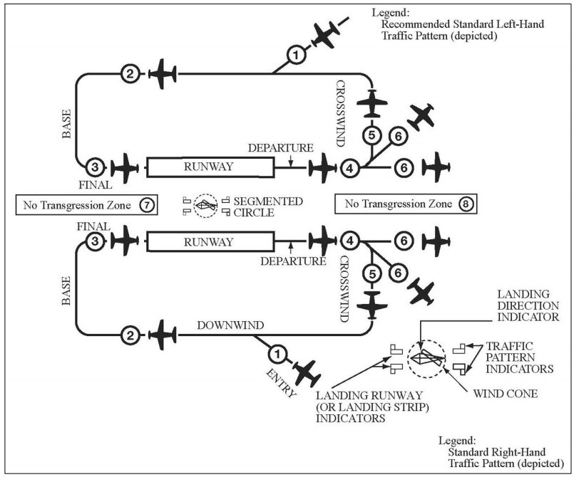
Pattern altitude for piston aircraft: 1,000 ft AGL. Turbine aircraft: 1,500 ft AGL. Traffic patterns are left-hand by default. Right-hand patterns are marked on sectional charts with an "RP" notation in the airport data block and published in the Chart Supplement. The preferred entry to a non-towered airport is a 45° entry to the downwind leg on the traffic side of the pattern, per AIM §4-3-3.
The traffic pattern — flying it correctly and safely
The standard traffic pattern altitude for light aircraft is 1,000 ft AGL above the airport elevation. Some airports use 800 ft or 1,500 ft — check the Chart Supplement or ATIS. The standard pattern is left-hand (all turns to the left) unless the Chart Supplement specifies a right-hand pattern for a specific runway. Right patterns are common when terrain or populated areas are on the left side of the runway.
Each leg of the pattern — what you're doing and why
Upwind leg: The runway heading after takeoff. Climb to approximately 400–500 ft AGL before beginning the crosswind turn. At a non-towered airport, announce your intentions on CTAF before takeoff and as you depart the pattern.
Crosswind leg: Perpendicular to the runway, climbing to pattern altitude. Turn crosswind when clear of the departure end of the runway — typically at 300–500 ft below pattern altitude. The crosswind leg is the transition to pattern altitude.
Downwind leg: Parallel to the runway, opposite direction of landing. This is where you configure the aircraft: reduce power to approximately 2,100 RPM (varies by aircraft), apply carb heat, and when abeam the landing threshold (the runway numbers), begin descending. Apply first notch of flaps abeam the numbers in many training aircraft. Announce "abeam the numbers" on CTAF at non-towered airports.
Base leg: Perpendicular to the runway, descending. Turn base when the runway threshold is approximately 45 degrees behind your shoulder — if you wait until it's 90 degrees, you'll overshoot final. Apply additional flaps. Announce "turning base" at non-towered airports.
Final approach: Aligned with the runway, descending to land. Full flaps (if appropriate for conditions). Stabilized approach means: on centerline, on glidepath, at target airspeed, in final configuration — all by 500 ft AGL at the latest. An unstabilized approach should result in a go-around, not an attempt to salvage the landing.
Non-towered airport operations — CTAF and self-announce
At non-towered airports, pilots use the Common Traffic Advisory Frequency (CTAF) to self-announce their position and intentions. There is no ATC — pilots coordinate with each other. Best practice is to monitor CTAF well before entering the airport area (10 miles out) to build a mental picture of who's in the pattern and where. Announce when you're 10 miles out with airport name, aircraft type, position, and intention. Announce at each pattern leg transition. Listen actively and update your mental picture.
The recommended pattern entry at a non-towered airport is a 45-degree entry to the downwind midfield — you approach from a 45-degree angle to join the midpoint of the downwind leg. This entry allows you to see and be seen by traffic already in the pattern. Straight-in approaches (final only, no pattern) are sometimes used but require extra caution — announce early and often, and be prepared for traffic that doesn't see you coming straight in.
Go-around — the most underused safety tool
A go-around is not a failure — it's a tool. Any time an approach becomes unstabilized, any time another aircraft is on the runway, any time you feel uncertain about the landing, go around. The procedure: full power, pitch to climb attitude, retract flaps incrementally (not all at once — a sudden flap retraction at low altitude and slow speed can cause a rapid sink), climb to pattern altitude, and re-enter the pattern. Announce the go-around on CTAF. The cost of a go-around is a few minutes and a few dollars of fuel. The cost of pressing a bad approach to landing can be much higher.
Lesson 6 — Airport Signs and Markings
Runway markings in detail — AIM §2-3
Runway markings are white on the paved surface. The full set of markings for an instrument runway includes:
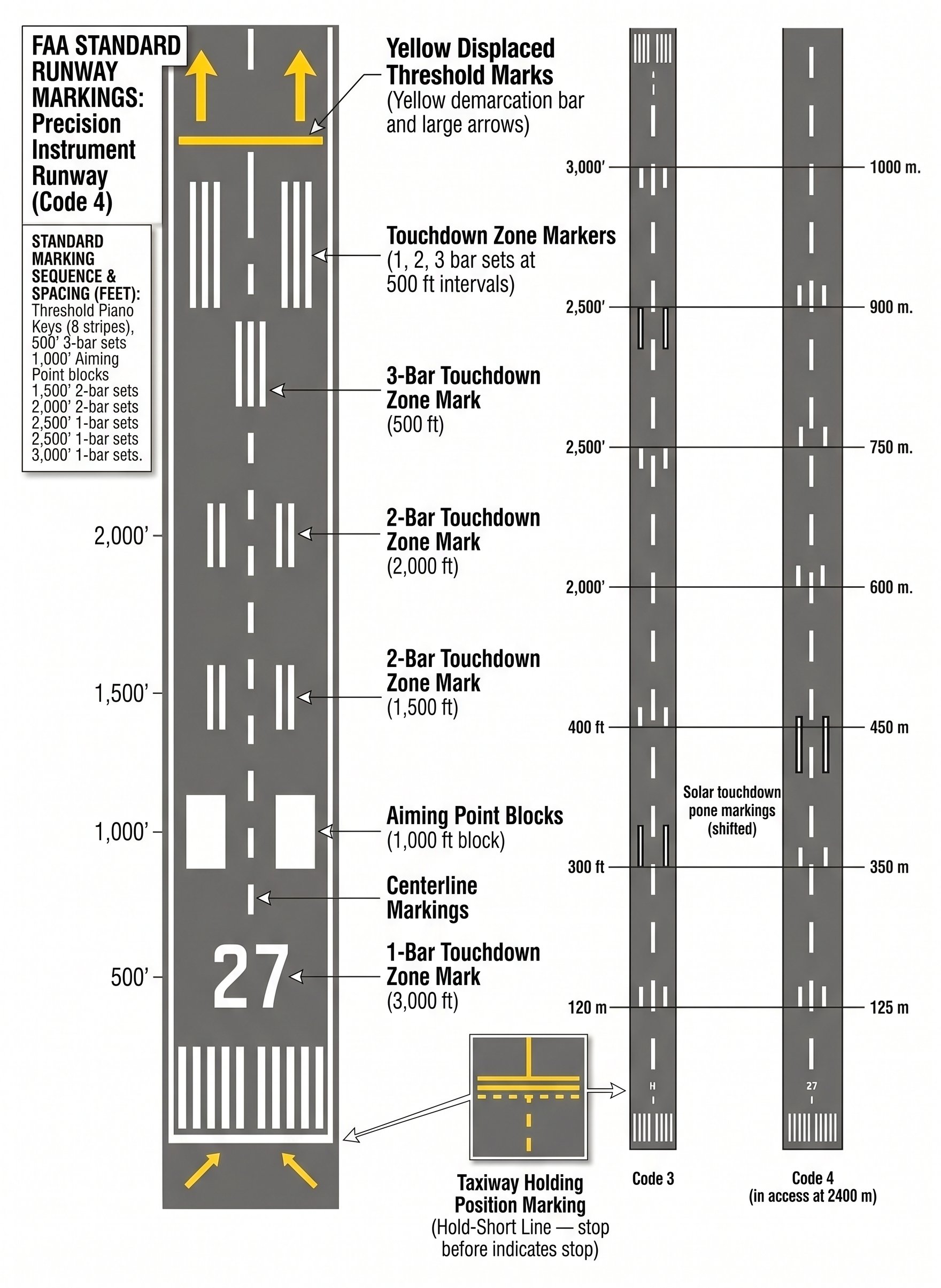
- Threshold markings: Parallel white stripes across the runway beginning — the landing threshold. The number of stripes varies by runway width (4 stripes on 60 ft runways up to 16 on 200 ft runways). Aircraft shall not land before the threshold. Reference: AIM §2-3-3.
- Displaced threshold: White arrows on the pavement before the threshold, followed by threshold markings. The area before the displaced threshold may only be used for taxiing, takeoff, and landing rollout — not as a landing area. Reference: AIM §2-3-4.
- Touchdown zone markings: Groups of white bars 500 ft apart in the first 3,000 ft of runway — the recommended landing area.
- Centerline: White dashed stripe down the runway. Maintain alignment during takeoff roll and landing rollout.
- Runway side stripes: Solid white lines defining runway edges, especially important at night and in low visibility.
Reading the airport surface — what every sign and marking means in practice
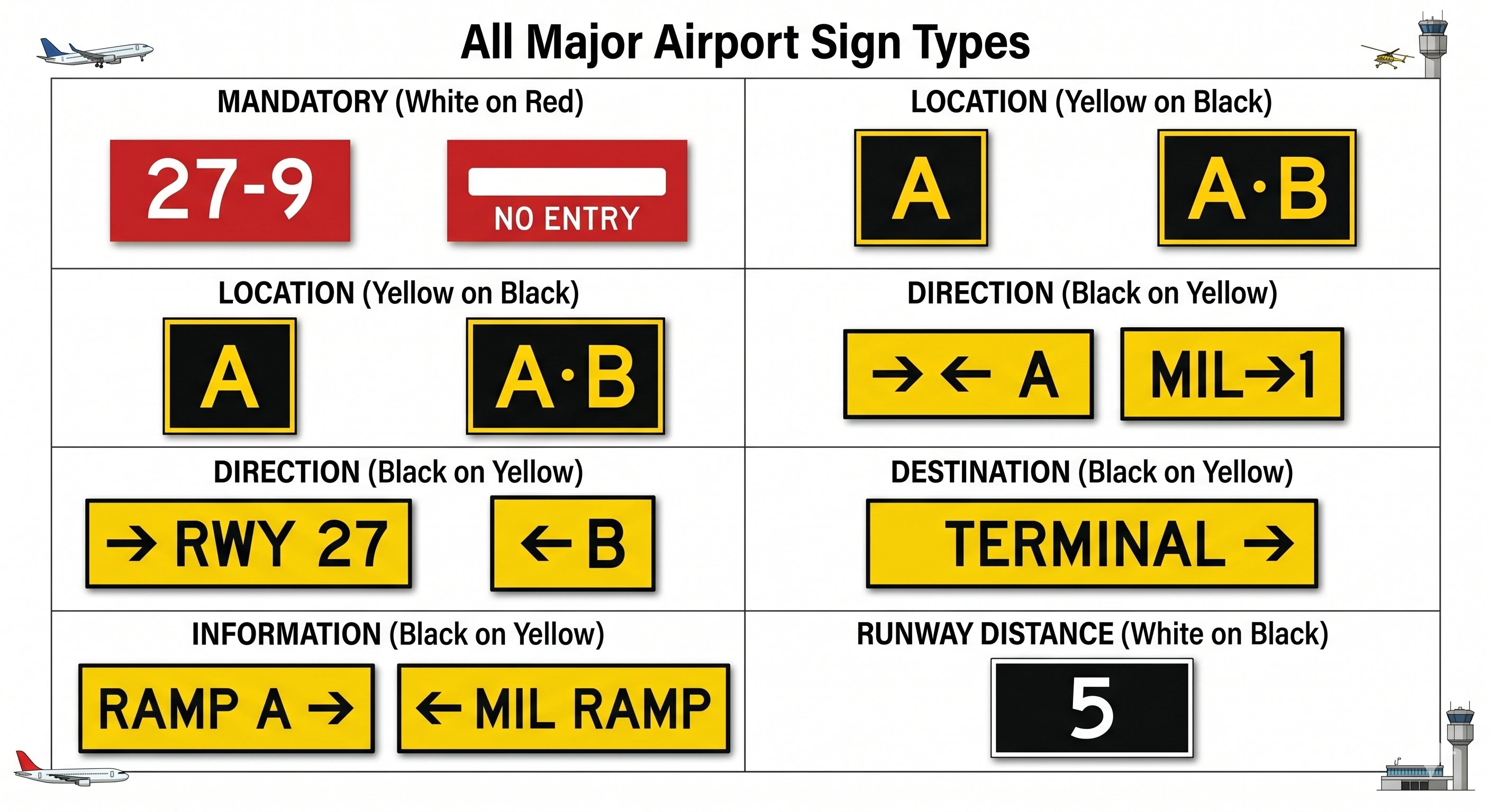
Airport signs and markings are standardized by the FAA. Every airport in the US uses the same system — once you know it, you can navigate any airport surface confidently. The key is to internalize the color system first, then the specific signs follow logically.
The hold short line — the most important marking on the airport
The runway holding position marking is two solid yellow lines and two dashed yellow lines painted across the taxiway. This is the hold short line — the boundary between the taxiway and the runway safety area. Never cross this line without an explicit ATC clearance (at towered airports) or without ensuring the runway is clear (at non-towered airports).
The orientation of the lines tells you which side to hold on: the solid lines face the runway — if you're approaching the runway and see solid lines, stop there. If you're exiting the runway and see dashed lines ahead, you've cleared the hold-short area. The simple rule: solid lines toward the runway = hold here.
Runway incursions — unauthorized entry onto an active runway — are one of the most dangerous situations in aviation and the FAA's top safety priority. Most runway incursions involve pilots missing or misreading hold-short signs and markings. Always read back hold-short instructions with the runway number. Look both ways before crossing any runway even after receiving clearance. When in doubt — stop and ask ATC for clarification.
Runway markings — what the paint on the runway tells you
Threshold markings: White stripes at the runway end — the number of stripes indicates runway width category. The piano keys (broad white stripes) mark the beginning of the landing area. Displaced threshold (white arrows leading to the threshold bar) means you can taxi and take off from that section but must not land before the threshold bar.
Runway numbers: The magnetic heading of the runway divided by 10 and rounded to the nearest 10 degrees. Runway 27 runs roughly 270° (west). Runway 09 runs roughly 090° (east). When you're on a heading of 270° approaching runway 27, the runway numbers are right-side up from the cockpit — that's the visual confirmation you have the right runway.
Touchdown zone markings: Groups of white rectangles on either side of the centerline in the first 3,000 feet of the runway. These are aiming points — you should aim to touch down in this zone, not beyond it. The first pair of rectangles (the "1,000 ft markers") are your target landing zone in most training aircraft.
Centerline: White dashes down the middle of the runway. Keep the nose wheel tracking the centerline on takeoff and landing. Drifting off centerline on takeoff, especially in crosswind conditions, can lead to runway departures.
Lesson 7 — Airport Lighting Systems
Visual Glideslope Indicators — PAPI and VASI
Visual glideslope indicators provide precise glidepath guidance during approach, supplementing ILS or serving as the primary approach reference for visual approaches. They are the most important approach lighting system for VFR pilots to understand.
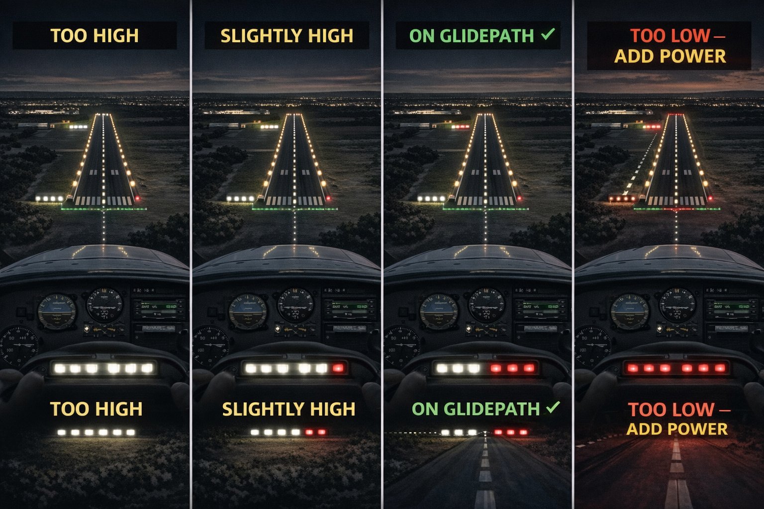
VASI (Visual Approach Slope Indicator) uses two bars of lights — near and far — each showing red or white depending on your angle to the glidepath. White over white = too high. Red over white = on glidepath. Red over red = too low. See AIM §2-1-4 for complete VASI/PAPI configurations.
REIL (Runway End Identifier Lights) are two synchronized flashing white strobe lights, one on each side of the runway threshold, installed to help pilots rapidly identify the approach end of a runway. Extremely valuable at night or when the airport is difficult to distinguish from surrounding lights. Reference: AIM §2-1-5.
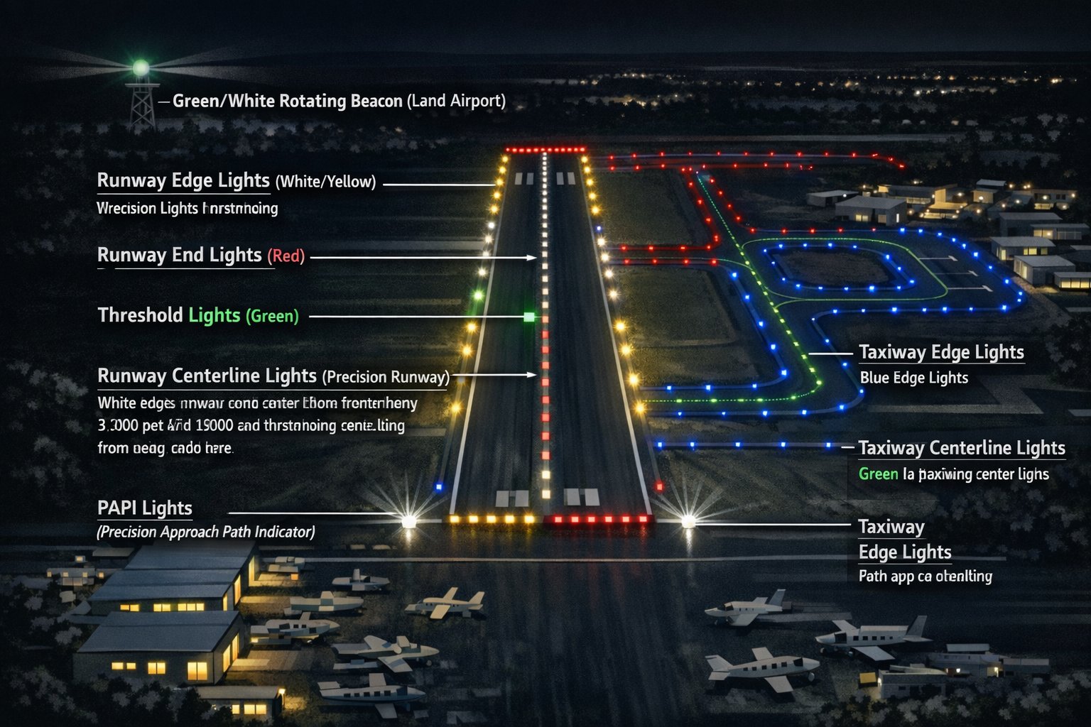
Runway and taxiway edge lighting
Per AIM §2-1-6, runway edge lights are white — except: the last 2,000 ft or last half of the runway (whichever is less) are yellow, providing a caution zone warning of the runway end. The very last edge lights at the end of the runway are red (viewed from the runway).
Taxiway edge lighting is blue. This is the key distinction at night: blue = taxiway, white/yellow = runway. Taxiway centerline lights are green. Runway centerline lights (on instrument runways) are white, transitioning to alternating red-white in the last 3,000 ft, and then solid red in the last 1,000 ft — giving pilots a clear visual count-down to the runway end.
Pilot-Controlled Lighting (PCL)
Many non-towered airports have pilot-controlled lighting — the approach and runway lights can be activated by the pilot keying the microphone on the CTAF frequency a specified number of times within 5 seconds. The frequency and click count are published in the Chart Supplement. Typically: 7 clicks = high intensity, 5 clicks = medium, 3 clicks = low. The lights stay on for 15 minutes after activation. Reference: AIM §2-1-22.
VASI and PAPI — reading the lights to stay on glidepath
Visual approach slope indicators are among the most important navigation aids for landing — yet many student pilots underuse them. Here's the practical guide to reading VASI and PAPI:
PAPI (Precision Approach Path Indicator): Four lights in a row on the left side of the runway. Each light shows red below the glidepath or white above it, depending on your angle relative to the calibrated glidepath (typically 3 degrees). Reading PAPI:
- 4 white: You are well above the glidepath — descend immediately.
- 3 white, 1 red: Slightly high — begin descending slightly.
- 2 white, 2 red: On glidepath — maintain current descent rate. This is the target.
- 1 white, 3 red: Slightly low — add power, reduce descent rate slightly.
- 4 red: Dangerously low — add power immediately, consider going around.
The PAPI mnemonic: "white over white, you're alright; red over red, you're dead." Technically this refers to the two-light VASI, but the principle applies — any all-red indication means you are critically low.
Runway edge lights and what the colors tell you
Runway edge lights are white — except at the last 2,000 feet of the runway (or the last half of the runway, whichever is less), where they turn yellow to warn you that you're approaching the departure end. If you see yellow runway edge lights during landing rollout, you have 2,000 feet or less of runway remaining — time to ensure you're slowing sufficiently.
Runway end lights are red — facing the runway (you see red when approaching the end from within the runway). This is the visual signal that you've reached the pavement's end.
Threshold lights are green on the approach side — the green lights mark the beginning of the landing surface. The same lights are red on the departure side, protecting departing aircraft from runway intrusions at the threshold.
Pilot-controlled lighting (PCL) — how to turn on the lights at night
Many non-towered airports use pilot-controlled lighting — a system where pilots activate the runway lights by clicking the microphone on the CTAF frequency. The standard system:
- 7 clicks in 5 seconds: High intensity (maximum brightness)
- 5 clicks in 5 seconds: Medium intensity
- 3 clicks in 5 seconds: Low intensity
The lights stay on for 15 minutes after activation. On night cross-country flights, activate PCL when you're approximately 10 miles out so the airport is illuminated when you arrive. If the lights are already on but dimmer than you'd like, click 7 times to bring them to high intensity — the timer resets with each activation. The CTAF frequency used for PCL is published in the Chart Supplement for each airport.
Airport beacon — what it means and why it matters at night
The rotating airport beacon operates during the hours of darkness and sometimes during the day when the weather is below VFR minimums (less than 1,000 ft ceiling or less than 3 miles visibility). A rotating green-white beacon means a civilian land airport. A rotating white-white (or white-green-white) beacon means a military airport. A green-yellow-white beacon indicates a lighted water airport. A white-white beacon at a land location indicates a landmark or obstruction light — not an airport.
The critical implication: if you see a rotating airport beacon during daylight hours, Special VFR rules or IFR conditions may exist at that airport. This is a visual cue to check weather immediately before entering that airport's area.
Lesson 8 — Special Use Airspace and Light Gun Signals
| Type | Authorization? | Chart | FAR/AIM reference |
|---|---|---|---|
| Prohibited | Never — no entry possible | Blue hash | 14 CFR §73.11 · AIM §3-4-2 |
| Restricted | Required from controlling agency | Blue hash | §73.13 · AIM §3-4-3 |
| Warning | Not required (offshore) | Blue hash | AIM §3-4-4 |
| MOA | Not required | Magenta hash | AIM §3-4-5 |
| Alert Area | Not required | Blue hash (Alert) | AIM §3-4-6 |
| National Security | Required | Blue hash | AIM §3-4-7 |
Light gun signals — AIM §4-3-13
When radio communication is lost, ATC communicates using a light gun — a device that projects colored light signals visible from the runway and traffic pattern. Per AIM §4-3-13, you must acknowledge receipt of light gun signals by rocking your wings in flight (or flashing landing lights when cleared to land), or by moving ailerons and rudder for ground signals.
| Signal | Aircraft in flight | Aircraft on ground |
|---|---|---|
| Steady green | Cleared to land | Cleared for takeoff |
| Flashing green | Return for landing | Cleared to taxi |
| Steady red | Give way — continue circling | STOP |
| Flashing red | Airport unsafe — do not land | Taxi clear of runway/landing area |
| Flashing white | (Not used) | Return to starting point |
| Alt. red/green | Exercise extreme caution | Exercise extreme caution |
- Class A: 18,000–60,000 ft MSL, IFR only, ATC clearance required. §91.135.
- Class B: ATC clearance (specific words) + Mode C + ADS-B + PPL. 3 SM clear of clouds. 30 nm Mode C veil. §91.131.
- Class C: Two-way comms (call sign acknowledged) + Mode C + ADS-B. 3 SM / 500-1,000-2,000. §91.130.
- Class D: Two-way comms only. Reverts to E or G when tower closed. §91.129.
- Class G day: 1 SM / clear of clouds below 1,200 AGL. Most permissive in NAS. §91.155.
- Signs: White/Red = mandatory (stop/hold — AIM §2-2-3). Yellow/Black = location. Black/Yellow = direction.
- PAPI: 2W 2R = on glidepath. 4R = below glidepath. 4W = above. AIM §2-1-4.
- Runway lights: white (yellow last 2,000 ft, red last lights). Blue = taxiway. AIM §2-1-6.
- Hold-short lines: two solid + two dashed yellow. Solid side faces the runway. Never cross without clearance. AIM §2-3-5.
- Light guns: Steady green = cleared to land (air) or takeoff (ground). Steady red = give way (air) or STOP (ground). AIM §4-3-13.
- Check NOTAMs before every flight — runways, navaids, TFRs. Use 1800wxbrief.com or the sectional app NOTAM overlay.
Navigating special use airspace on your cross-country
When planning a cross-country, your route may cross or pass near special use airspace. The key distinction for practical planning:
Prohibited areas (P-xxx): Always avoid. No exceptions. These include Camp David (P-40), Washington DC (P-56), and other sensitive locations. Even if your GPS routes through one, you must go around.
Restricted areas (R-xxx): Check with the controlling agency or Flight Service before entering. When inactive (the hot times have passed), you may be able to transit with ATC permission. When active ("hot"), treat like prohibited — do not enter. Restricted areas are shown on sectionals with blue hatching and labeled with their designation and altitude limits.
MOAs (Military Operations Areas): When active, ATC cannot provide VFR separation from military traffic. You can legally enter an active MOA VFR, but ATC will warn you and you're on your own for traffic avoidance. Military jets in MOAs can exceed 300 knots at low altitude — see-and-avoid is extremely challenging. Best practice: route around active MOAs. If you must transit, do it quickly and watch for high-speed traffic.
Warning areas: Located over international waters (usually offshore). Similar to restricted areas but over water where the FAA has limited jurisdiction. Use caution — military and weapons activity occurs here.
Lesson 9 — VFR Weather Minimums and the Class E / G Detail
The most tested airspace topic on the written exam is VFR weather minimums — specifically the differences between airspace classes and the common trap questions around Class E and G. This lesson works through the complete picture.
The complete VFR minimums table
VFR weather minimums are established under FAR 91.155. The rule of thumb is "3 and 3" for most controlled airspace — 3 statute miles visibility and 3 cloud clearances (500 below, 1,000 above, 2,000 horizontal). But the exceptions are where the test lives.
The three exam traps in VFR minimums
Trap 1: Class B is "clear of clouds" not "500/1,000/2,000." Students often apply the standard controlled airspace rule to Class B. Class B is different — you need 3 SM visibility and must remain clear of clouds (no specific distance requirement). This is because ATC provides separation services to all aircraft in Class B, so you don't need the same cloud buffer.
Trap 2: Class E at or above 10,000 feet MSL has stricter requirements. Above 10,000 MSL you need 5 SM visibility and 1,000 below / 1,000 above / 1 SM horizontal. The reason: higher airspeeds mean aircraft close faster. A 2-mile separation at 250 knots provides little warning time.
Trap 3: Class G day below 1,200 AGL is 1 SM clear of clouds. This is the most permissive VFR minimum in the system. Flying in Class G (uncontrolled airspace) in daytime at low altitude legally requires only 1 statute mile visibility and staying clear of clouds. This does not mean it's safe — just legal.
Where Class E actually begins
Class E's surface is not always at 1,200 ft AGL. Understanding where Class E begins matters because it determines which minimums apply near the surface. Three different floors:
- 1,200 ft AGL — the default. Most of the US at cruise altitude is Class E beginning at 1,200 AGL.
- 700 ft AGL — shown on sectional charts as magenta shading around airports with instrument approaches. Class E begins at 700 AGL to protect IFR aircraft transitioning to/from approaches.
- Surface — shown as dashed magenta rings. Class E goes all the way to the surface at some airports without control towers. These airports require VFR minimums even for surface ops.
When Class E extends to the surface, VFR weather minimums for Class E (not Class G) apply — 3 SM and 500/1,000/2,000. This matters for weather decision-making near non-towered instrument airports.
Applying VFR minimums to real go/no-go decisions
Knowing the minimums is one thing. Applying them to a real flight decision is another. Here's a practical framework:
Check the current METAR: Is ceiling BKN or OVC? That's the ceiling. Is it above 1,000 ft at your destination? Is visibility 3 SM or more? If yes to both — VFR legal. But also ask: is it trending up or down? A 1,200 ft ceiling that was 2,500 ft an hour ago is a warning sign.
Check the TAF: What are conditions forecast for your arrival time? If the TAF shows BECMG OVC008 during your ETA window, the ceiling is forecast to drop to 800 ft — below VFR minimums. Legal right now doesn't mean legal when you get there.
The "3-1 rule" for ceiling and visibility: Many experienced VFR pilots use a personal minimum of ceiling at least 3,000 ft and visibility at least 5 SM for cross-country flight — well above the legal minimum. This buffer provides margin for unexpected deterioration. The legal minimum of 1,000/3 is the floor, not the standard.
Night VFR minimums vs. day: The legal minimums are the same day and night. The practical minimums should be higher at night — darkness removes visual reference to terrain and weather. Clouds that are easy to avoid in daylight (you can see them and go around) are invisible at night until you're in them. Many VFR pilots establish personal night minimums of 5,000 ft ceiling and 7+ SM visibility.